

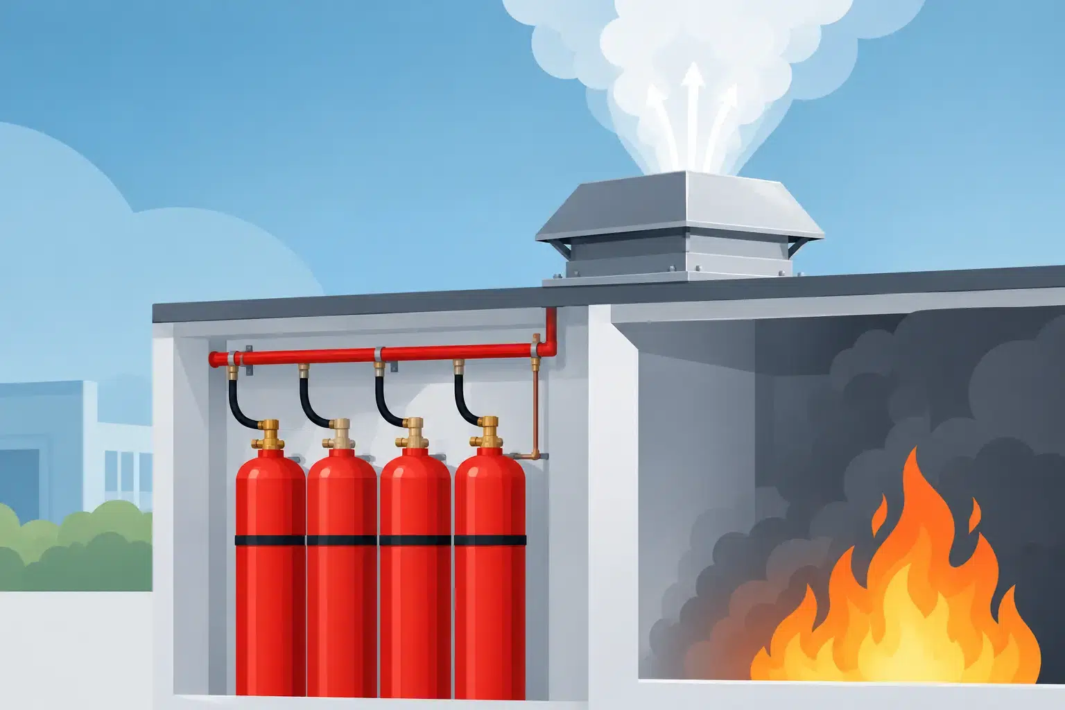
A gaseous fire-suppression system can extinguish a developing fire in seconds, but its discharge also changes the pressure inside the protected enclosure. Without a properly engineered route for that pressure to escape, doors, ceilings, walls and glazed panels can become the weakest part of the system. Overpressure vents for fire suppression are designed to manage this force while helping the enclosure retain the extinguishing concentration needed to protect critical assets.
For server rooms, data centres, electrical switchrooms, control rooms, archives and other high-value spaces, pressure relief is not an optional add-on. It is a key part of an effective, standards-led suppression design.
Why gaseous suppression creates room pressure
When an inert gas or clean agent system discharges, a large volume of extinguishing agent enters the enclosure in a very short period. This is essential to achieve the required design concentration quickly enough to control the fire. However, the incoming agent displaces air, creating a temporary increase in enclosure pressure.
The level of pressure depends on several factors: the agent selected, total cylinder capacity, discharge time, nozzle arrangement, enclosure volume, room construction and any existing leakage paths. Inert gas systems such as IG55, IG541, IG01 and IG100 can produce significant pressure effects because they require larger agent volumes. Clean-agent systems, including HFC227ea, may present different pressure characteristics, but still require assessment.
If pressure is not relieved safely, the discharge can damage building fabric or force open doors and access panels. That can affect compartmentation, create a route for agent loss and leave the protected area unable to hold the required concentration for the specified hold time.
How overpressure vents for fire suppression work
An overpressure vent is installed in the boundary of the protected enclosure, usually within a wall, door or purpose-designed duct arrangement. During discharge, the vent opens when the room pressure reaches its operating threshold. It allows displaced air and excess pressure to pass into a suitable adjacent area or to atmosphere, then closes when the pressure returns to normal.
The objective is carefully balanced. The vent must provide enough free area to limit pressure to a level the enclosure can tolerate, without creating an uncontrolled opening that compromises the agent concentration. This is why vent selection cannot be based simply on room size or a standard grille detail.
Many applications require consideration of both positive and negative pressure. Positive pressure occurs as agent enters the room. Negative pressure can occur afterwards, for example as hot gases cool or as the protected space returns towards normal conditions. Depending on the system and enclosure, a bi-directional pressure relief vent may be appropriate. The correct arrangement should follow the agent manufacturer’s calculations, enclosure characteristics and project specification.
Pressure relief is not smoke ventilation
Overpressure vents are sometimes mistaken for smoke vents or general ventilation grilles. They serve a different purpose. A pressure-relief vent is designed around the short, controlled pressure change created by suppression discharge. It must also preserve the fire-resisting and environmental performance required of the room boundary.
A permanently open louvre, for example, may reduce pressure but could undermine room integrity, permit excessive agent escape and introduce unwanted airflow into a sensitive environment. In a data centre or switchroom, it may also create security, dust-control or weathering concerns.
Why room integrity and vent design must be considered together
A gaseous suppression system relies on the enclosure retaining extinguishant at the correct concentration for a defined period. This retention period gives the agent time to prevent re-ignition while emergency response and investigation take place. If the room has unsealed cable penetrations, gaps around doors, unprotected service routes or poorly integrated vents, the concentration may decay too quickly.
Room integrity testing is therefore closely connected to pressure-relief design. A door fan test can identify leakage and help establish whether the enclosure is likely to retain agent for the required period. It does not replace pressure vent calculations, and vent calculations do not replace integrity testing. Both are needed to confirm the enclosure will perform as intended.
This relationship creates a practical challenge. Sealing a room more effectively can improve agent retention, but it may increase the pressure effect during discharge. Adding an inadequately selected vent may reduce pressure but create an excessive leakage path. The correct solution is an engineered combination of enclosure sealing, calculated relief area and appropriate vent operation.
What should be assessed before selecting a vent
The starting point is not the vent catalogue. It is a full understanding of the protected risk, the selected suppression agent and the enclosure itself. A competent design will examine the room volume and construction, the expected discharge profile, structural pressure limits and the route available for relieved air.
The destination for discharged air matters as much as the vent’s nominal free area. Relieving pressure into a small adjacent room, a ceiling void or an occupied circulation space may transfer the issue rather than resolve it. The receiving space must be suitable for the predicted airflow and pressure change. In some projects, ductwork is required to route relief safely to a designated area.
Designers also need to consider fire compartmentation. Any opening through a fire-resisting wall must be compatible with the required fire performance. The vent arrangement should not weaken the compartment that the suppression system is intended to protect. Coordination with mechanical, electrical and building teams is particularly important where there are suspended ceilings, raised floors, large cable routes or building-management interfaces.
Other project-specific considerations can include noise during discharge, external weather protection, security, dust ingress, acoustic requirements and access for inspection. In occupied spaces, the effects of agent discharge and airflow need consideration alongside the wider life-safety strategy.
Standards, calculations and commissioning
Gaseous suppression systems are commonly designed with reference to standards such as BS EN 15004, ISO 14520 and, where specified, NFPA 2001. The applicable standard, client specification, insurer requirements and agent manufacturer guidance will shape the design approach.
Pressure-relief calculations should be based on verified discharge data and the enclosure’s known or assessed pressure tolerance. A calculation provides the required relief area, but installation quality remains vital. A vent fitted into an unsealed wall opening, obstructed by later building works or connected to an unsuitable void may not perform as designed.
Commissioning should confirm that the vent has been installed in the intended orientation, is accessible for inspection and is free to operate. The suppression system controls, detection, warning devices, abort arrangements and shutdown interfaces should then be tested as an integrated system. Where the system protects a business-critical room, a demonstrated sequence of operation gives facilities and operations teams confidence in what will happen during an incident.
Common mistakes that create avoidable risk
The most frequent issue is treating pressure relief as a late-stage construction detail. By the time containment works are complete, a suitable route through the building fabric may be difficult and costly to create. Early design coordination avoids improvised solutions that compromise either the room or the system.
Another mistake is assuming that a room with obvious gaps does not need a vent. Uncontrolled leakage is not predictable pressure relief. It can vary with doors, damper positions and construction changes, while also making it harder to retain extinguishing concentration.
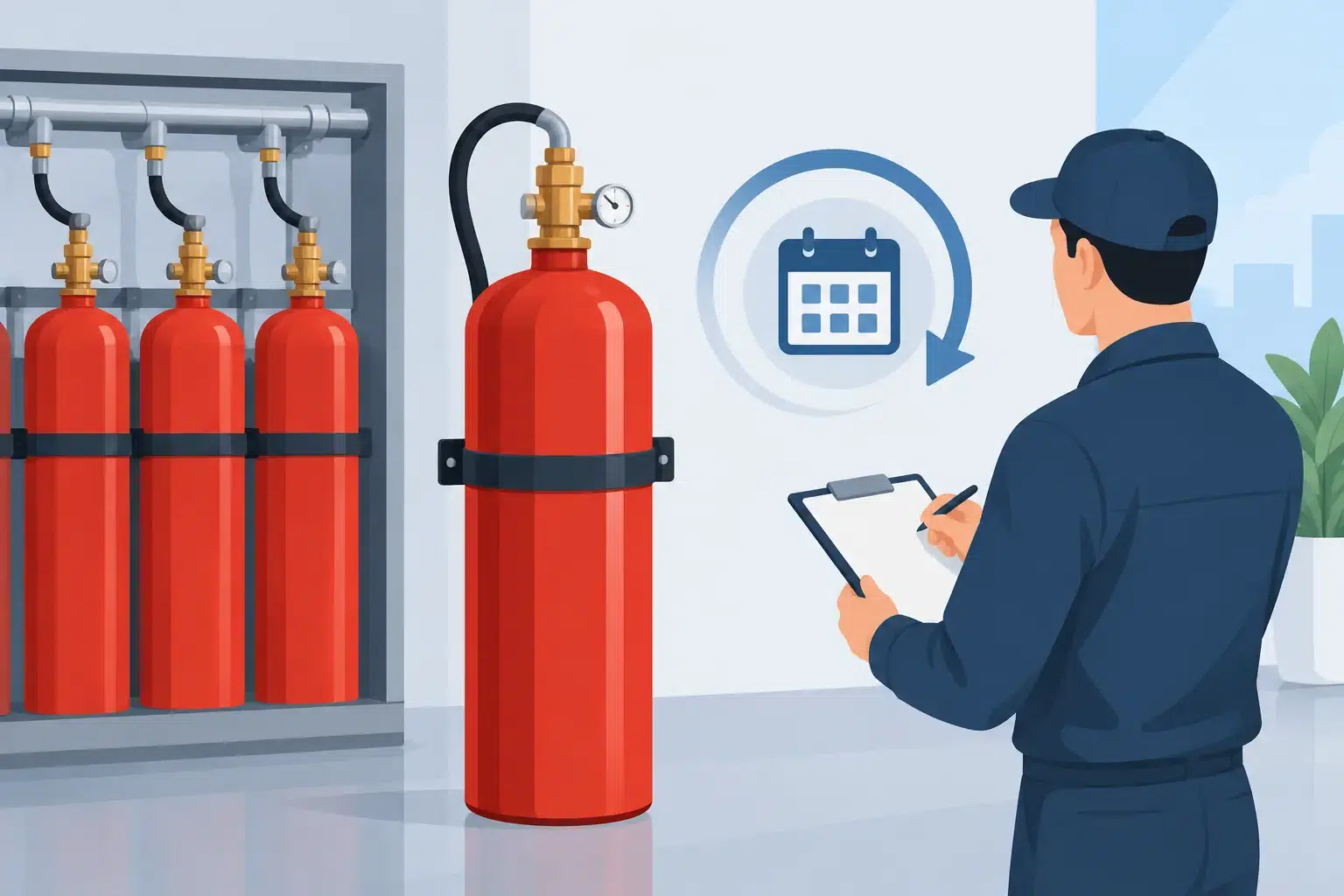
Maintenance is sometimes overlooked as well. Overpressure vents are mechanical components in a life-safety installation. They should be included in planned inspection and maintenance, particularly where dust, corrosion, accidental impact or refurbishment could affect their movement or effective area.
A practical approach for critical environments
For facilities managers and project teams, the most effective route is to consider pressure relief from the first risk discussion. Confirm what needs protecting, whether people may be present, the consequences of downtime and the suitability of inert gas, clean agent, CO2 or another suppression method. The enclosure, agent, detection, controls, pressure venting and integrity testing can then be designed as one coordinated solution.
Active Fire Suppression Ltd can manage this process from technical design and budgeting through installation, room sealing, testing, commissioning and ongoing maintenance. That single point of responsibility helps prevent gaps between the suppression design and the building works needed to support it.
A pressure vent may be a small part of the visible installation, but it has a direct bearing on whether a gaseous suppression system protects the room, the assets inside it and the continuity plan behind it. Discussing enclosure pressure early gives the project team more options, fewer late changes and a clearer route to dependable protection.
Leave A Comment
You must be logged in to post a comment.