

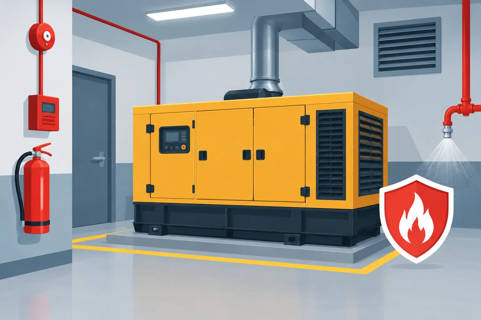
A standby generator should protect the site when mains power fails, not become the source of a longer and more damaging outage. Yet generator rooms bring together hot exhaust components, diesel or other fuel, lubricating oil, high-current electrical equipment and forced ventilation. Knowing how to protect generator rooms means addressing those hazards as one engineered fire strategy, rather than relying on a detector or portable extinguisher alone.
For facilities teams, the objective is clear: contain a developing incident early, protect people, avoid damage spreading beyond the generator enclosure and make a controlled return to service possible. The right solution depends on the generator type, fuel arrangement, room construction, occupancy, ventilation design, insurer expectations and the role that generator plays in the site’s continuity plans.
How to protect generator rooms with a layered design
A protected generator room needs several measures working together. Good housekeeping, fire-resistant construction and suitable detection reduce the likelihood of a small fault becoming a serious incident. Automatic suppression provides intervention when the room is unattended or conditions develop too quickly for manual action.
This layered approach matters because the most common hazards do not behave in the same way. An overheated bearing or electrical connection may produce smoke long before flames are visible. A pressurised fuel leak reaching a hot exhaust surface can create a rapidly growing flame fire. Fuel stored within or immediately outside the enclosure can also sustain a fire after electrical supplies have been isolated.
The design should begin with a practical review of the room and its operation. This includes the generator rating and duty cycle, fuel tank capacity and pipework routes, exhaust layout, cable entries, ventilation louvres, maintenance access and whether anyone is expected to enter during an alarm condition. A generator that supports life-safety systems, a data centre or a critical production line may justify a different level of protection from a set used only for limited resilience.
Control fuel, heat and ignition sources
Diesel supply and return lines should be protected from mechanical damage and routed away from unshielded hot surfaces wherever practicable. Isolation valves, leak management and appropriate bunding can limit the quantity of fuel available to a fire. Any day tank arrangement needs particular attention, including high-level alarms, overflow protection and safe separation from ignition sources.
Exhaust systems need suitable thermal shielding and clearance from combustible materials. Oil residue, packaging, rags and stored maintenance materials should not be allowed to accumulate in the room. These controls may sound basic, but they materially reduce the fire load that an automatic suppression system may have to deal with.
Electrical faults are another significant concern. Loose terminations, overloaded auxiliary circuits, degraded insulation and battery charger faults can all initiate a fire. Planned electrical inspection and thermographic surveys where appropriate can identify developing issues before they result in an emergency.
Use detection that reflects real room conditions
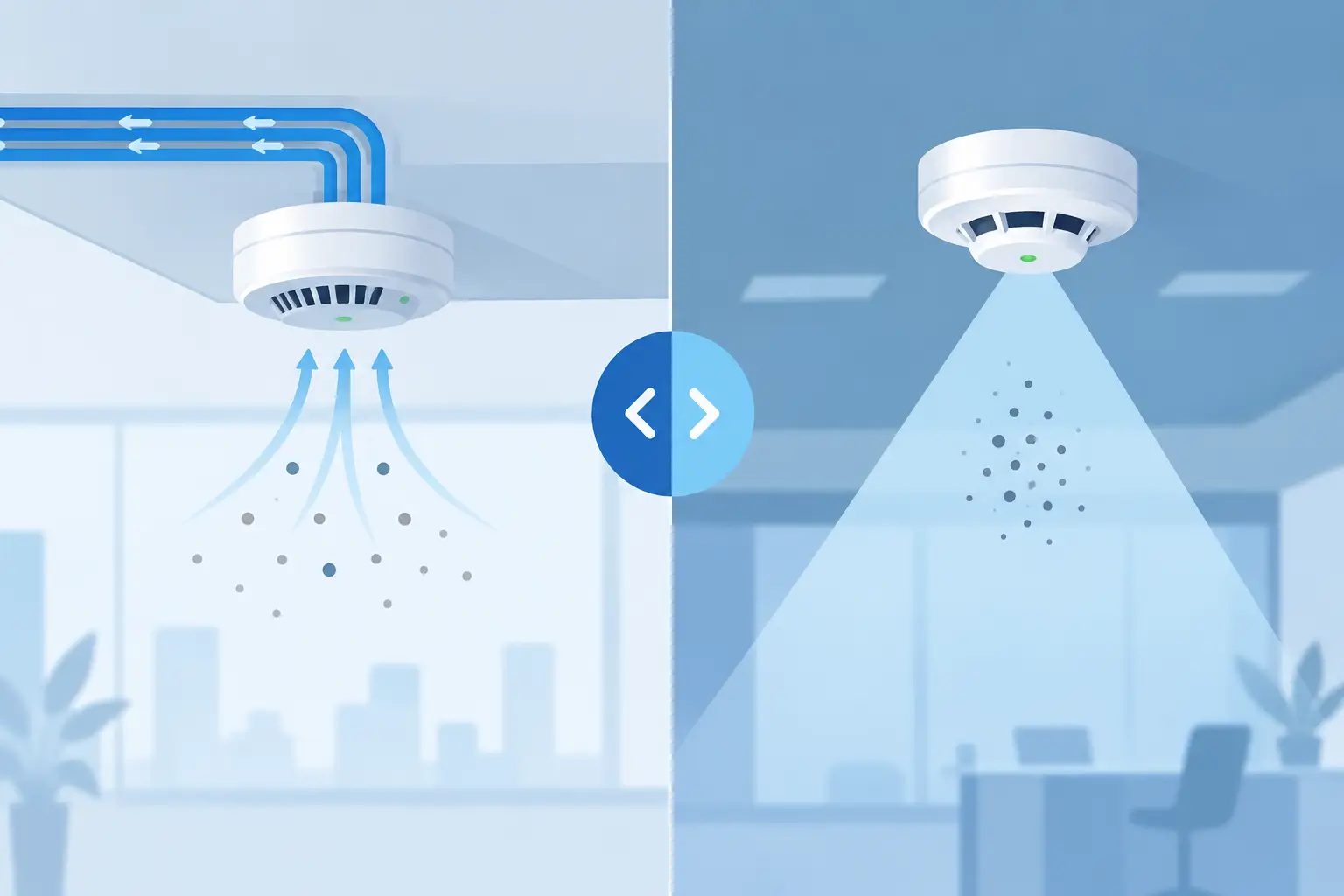
Conventional smoke, heat and multi-sensor detection may form part of the protection arrangement, but placement needs careful consideration. High airflow, dust, humidity and diesel exhaust can affect detector performance. A detector mounted without regard to ventilation patterns may respond too slowly, or generate unwanted alarms that reduce confidence in the system.
Aspirating smoke detection, including VESDA, can provide very early warning where the environment and air-sampling design support it. Flame detection can be particularly valuable where a fuel-fed fire may develop rapidly and direct line of sight can be maintained. Heat detection is often used as a dependable confirmation method in harsher conditions.
For higher-risk sites, the fire alarm cause-and-effect strategy should distinguish between an early warning and a confirmed fire condition. A pre-alarm can alert the facilities team to investigate. Confirmed detection from two suitable devices, or a detector and flame detector, can then start the suppression sequence. The exact logic must be designed around the risk, because acting too quickly could remove essential emergency power, while acting too late risks escalation.
Match automatic suppression to the generator room
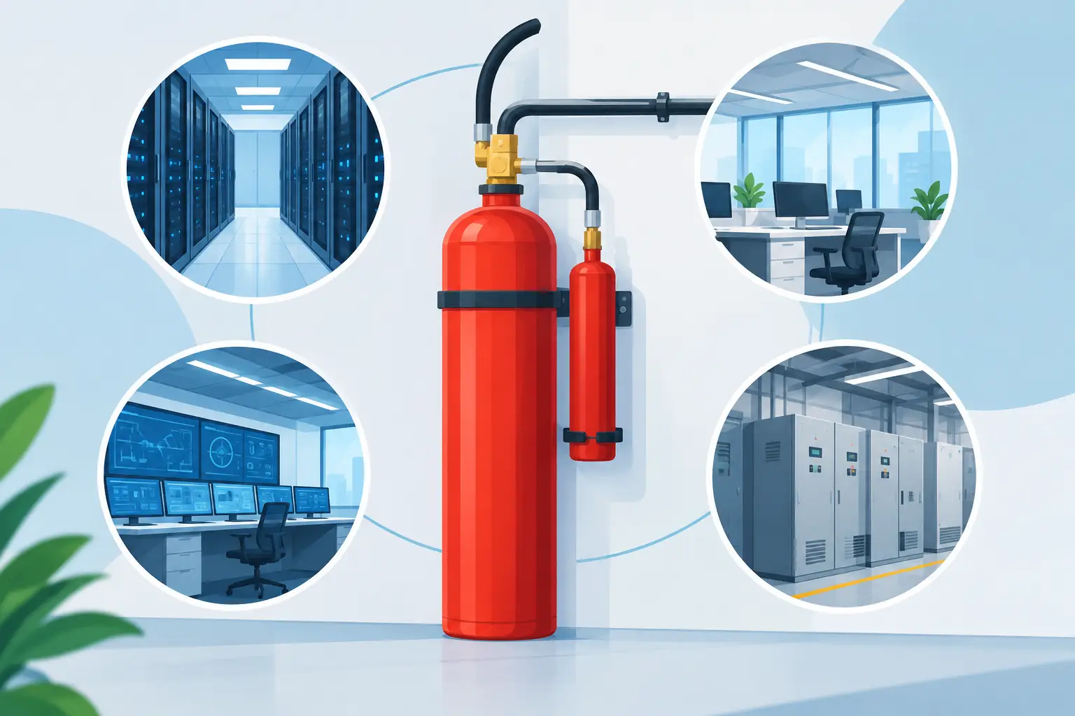
There is no single extinguishing agent that suits every generator enclosure. Total-flooding gaseous systems can be highly effective in an enclosed room, preventing the fire from continuing without the water damage associated with traditional sprinkler discharge. However, they depend on the room retaining the required extinguishing concentration for the specified hold time.
Inert gas systems such as IG55, IG541, IG01, IG100 and INERGEN® are established choices for suitable enclosures. They use naturally occurring gases and can be selected where environmental policy, agent storage, room volume and life-safety considerations align. Clean-agent systems using Novec 1230 or HFC227ea/FM200/FE227 may also be appropriate where a clean extinguishing medium and compact cylinder storage are priorities.
CO2 is an effective agent for certain machinery and fuel-fire applications, but it presents serious life-safety considerations because the discharge concentration is hazardous to people. Where CO2 is proposed, the design must include the necessary warning arrangements, time delays, manual abort facilities, signage, training and controlled access procedures. It is not a system to specify casually for a room that is regularly occupied.
The room itself can determine whether total flooding is viable. Generator rooms commonly have large supply and extract openings to manage heat, as well as exhaust penetrations and cable routes. Before a gaseous system discharges, ventilation may need to shut down and fire dampers or louvres may need to close. Fuel isolation and generator shutdown may also be part of the sequence, subject to the wider emergency-power strategy.
That creates a genuine operational trade-off. Stopping the generator can prevent a fire worsening, but may affect critical loads. Keeping it running can preserve power temporarily but may continue feeding heat, fuel or airflow into the fire scenario. The correct response should be agreed by operations, engineering, fire-risk and business-continuity stakeholders, then documented in the cause-and-effect matrix.
Where the room cannot be made sufficiently enclosed, a different suppression approach or changes to the enclosure and ventilation design may be necessary. An engineered assessment is more valuable than forcing a preferred agent into unsuitable conditions.
Seal, relieve and test the enclosure
Room sealing is not cosmetic work. Gaps around cable trays, pipe penetrations, doors, ducts and construction joints can allow extinguishing agent to escape. They can also allow smoke and fire to spread to neighbouring areas. Approved fire stopping and coordinated sealing works are therefore central to the performance of a gaseous suppression installation.
At the same time, discharge can create a pressure change within the enclosure. Correctly sized over-pressure vents may be needed to protect walls, doors and other building elements while allowing the system to achieve its design performance. Both the vents and room sealing must be considered during technical design, not treated as late-stage additions.
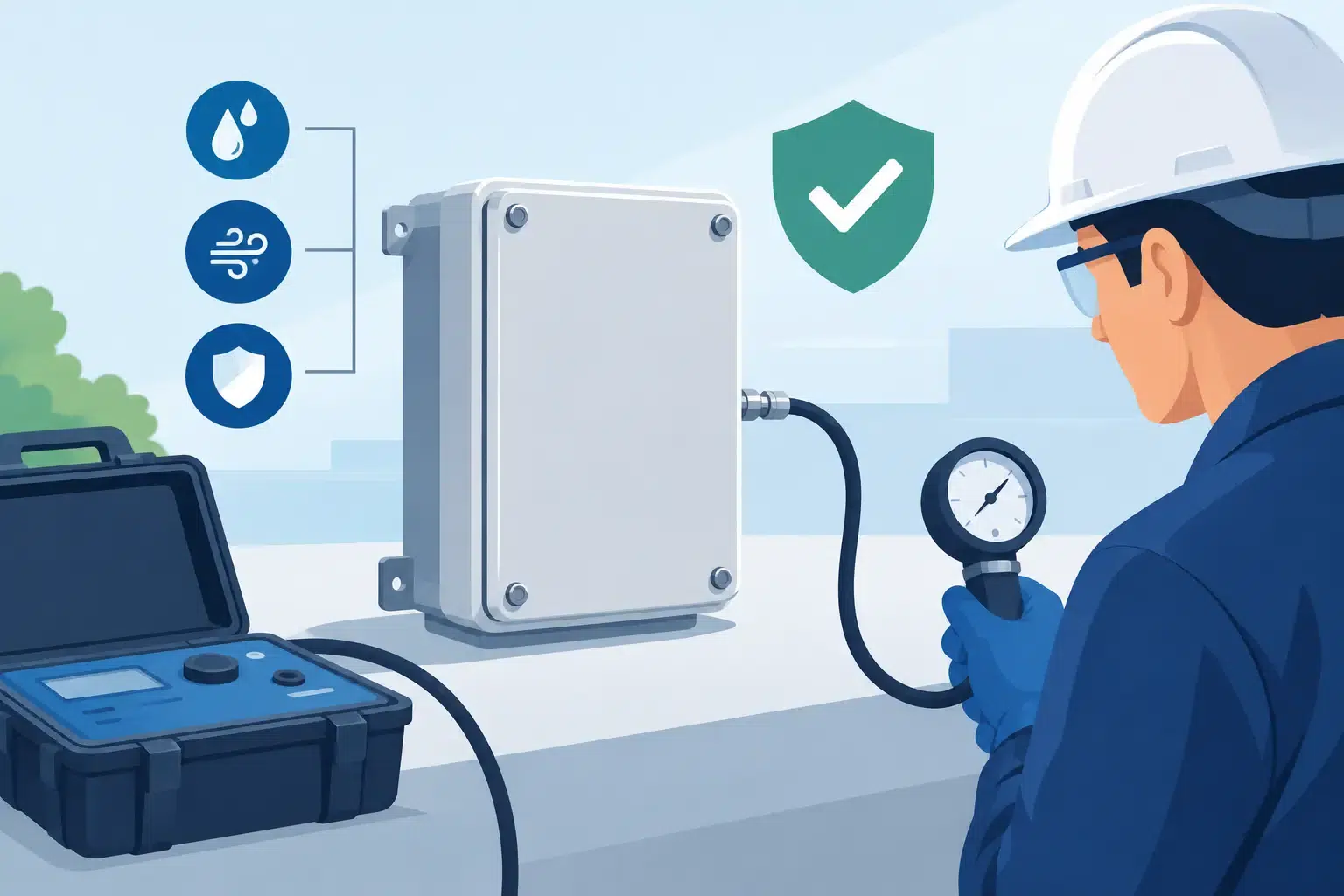
Once installed, a room-integrity test verifies whether the enclosure is likely to retain the required agent concentration. This test is particularly useful after building works, new cabling or alterations to ventilation, all of which can compromise a previously compliant room. It does not replace inspection, but it provides evidence that the enclosure remains capable of supporting the suppression design.
Make operation, maintenance and recovery part of the plan
A fire system is only as reliable as its testing and maintenance regime. Detection devices need periodic inspection and functional testing. Suppression cylinders, pipework, control panels, pressure-relief components, warning devices and interfaces with ventilation, fuel and generator controls all require planned checks by competent specialists.
Facilities teams should also rehearse what happens after an alarm. Staff need to understand evacuation routes, access restrictions, who contacts the generator service provider and how the room is declared safe for re-entry. After a discharge, the priority is not simply to restart the set. The cause of the fire must be investigated, fuel and electrical systems made safe, and the suppression system reinstated before normal reliance on the generator resumes.
Relevant British and European standards, fire-risk assessment duties, insurer requirements and manufacturer guidance should inform the final specification. For gaseous systems, this commonly includes design principles under BS EN 15004 alongside the applicable detection, alarm and installation requirements. The precise standards route depends on the chosen system and site conditions.
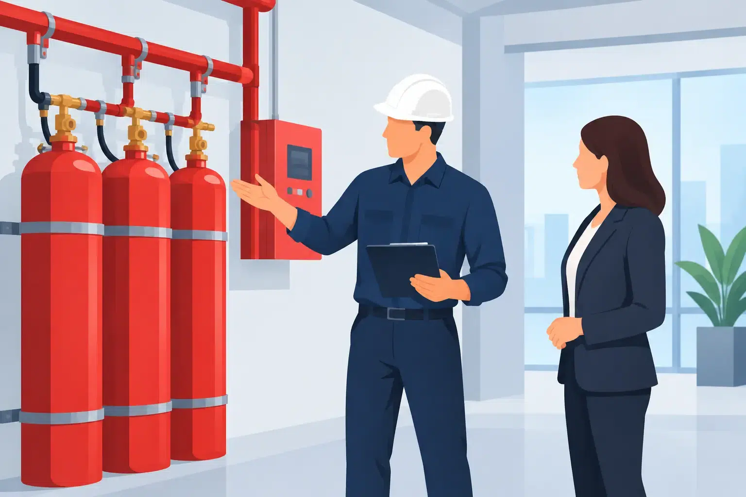
A generator room protection project works best when detection, suppression, enclosure integrity and control interfaces are managed as one scope. Active Fire Suppression can take that responsibility from initial risk discussion through design, installation, commissioning, demonstration and ongoing support, giving site teams a clear route from identified risk to tested protection.
The most useful next step is to walk the generator room with the people responsible for power, maintenance and continuity, then test one question honestly: if a fuel or electrical fire started here at 2 am, what would detect it, isolate it and stop it before the outage spreads?
Leave A Comment
You must be logged in to post a comment.