

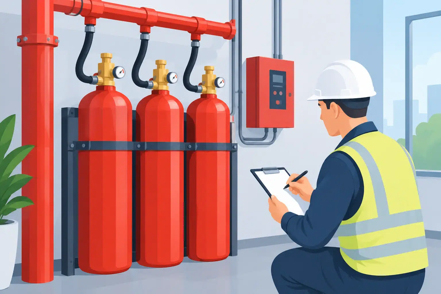
A fire suppression system is only as dependable as the evidence behind it. This fire suppression acceptance testing guide sets out what a UK business should expect before a new or upgraded system is handed over – whether it protects a server room, data centre, battery room, manufacturing process, archive or commercial kitchen.
Acceptance testing is not a box-ticking exercise after installation. It is the point at which the design, installed equipment, detection, controls, enclosure and site procedures are proved to work together. Done properly, it gives facilities and operations teams confidence that automatic intervention will occur as intended, while avoiding avoidable disruption, agent replacement costs and false discharge risk.
What acceptance testing needs to prove
The central question is straightforward: will the system detect the relevant fire condition, warn people, operate the required safety functions and deliver the extinguishing agent into a suitable enclosure or hazard area? The detail depends on the agent and application, but the test programme should demonstrate performance against the approved design, manufacturer instructions and applicable standards.
For gaseous systems, this commonly means considering BS EN 15004 alongside the relevant system approval and project specification. CO2 applications require especially careful attention to life safety, warning arrangements, lock-off controls and evacuation procedures because the agent can create a serious hazard to people. Kitchen wet-chemical, dry-powder and local-application systems have different operating principles, including the interface with fuel or power shut-offs.
A competent acceptance process also verifies the practical outcomes that matter to the business: the protected equipment can be isolated safely, alarms reach the right people, downtime is controlled and the system can be returned to service without uncertainty.
Fire suppression acceptance testing guide: the process
Start with the approved design, not the installed pipework
Testing should begin by reviewing the design information against the finished installation. This includes the cause-and-effect matrix, hydraulic or flow calculations where applicable, cylinder and nozzle schedules, cable drawings, battery calculations, room volume, agent concentration and any assumptions made during design.
This stage regularly identifies changes that need resolving before functional testing starts. A new cable tray, partition, suspended ceiling void, air-handling alteration or equipment layout change can affect detector coverage, agent distribution or enclosure integrity. In a server room, for example, an additional extract route can compromise hold time even when every control-panel indication appears correct.
The installer should confirm that cylinders, valves, nozzles, pipework, detectors, releasing controls, sounders, beacons, manual release points and abort controls are correctly located, labelled, supported and accessible. Components must be compatible with the listed system configuration rather than simply being physically connected.
Verify detection, releasing logic and interfaces
Most critical-area systems use cross-zoned detection or another confirmed releasing logic to reduce the chance of accidental discharge. Acceptance testing should prove each detection zone, the sequence of panel indications and the logic that moves the system from alarm to release.
The sequence matters as much as individual devices. Tests should confirm the correct pre-discharge warning period, audible and visual warning devices, release output and the reset process. They should also establish what happens when a detector faults, a manual release is operated, an abort control is held, a cylinder supervisory switch changes state or the panel loses mains power.
Interfaces require close coordination with other building systems. Depending on the risk, the release sequence may need to stop air-handling plant, close dampers, shut down equipment, release doors, notify a building management system, initiate remote monitoring or isolate electrical supplies. Each interface should be tested end to end, with responsibility agreed in advance. A signal shown at the suppression panel is not sufficient proof that a third-party system has acted.
Test the enclosure and pressure-relief arrangements
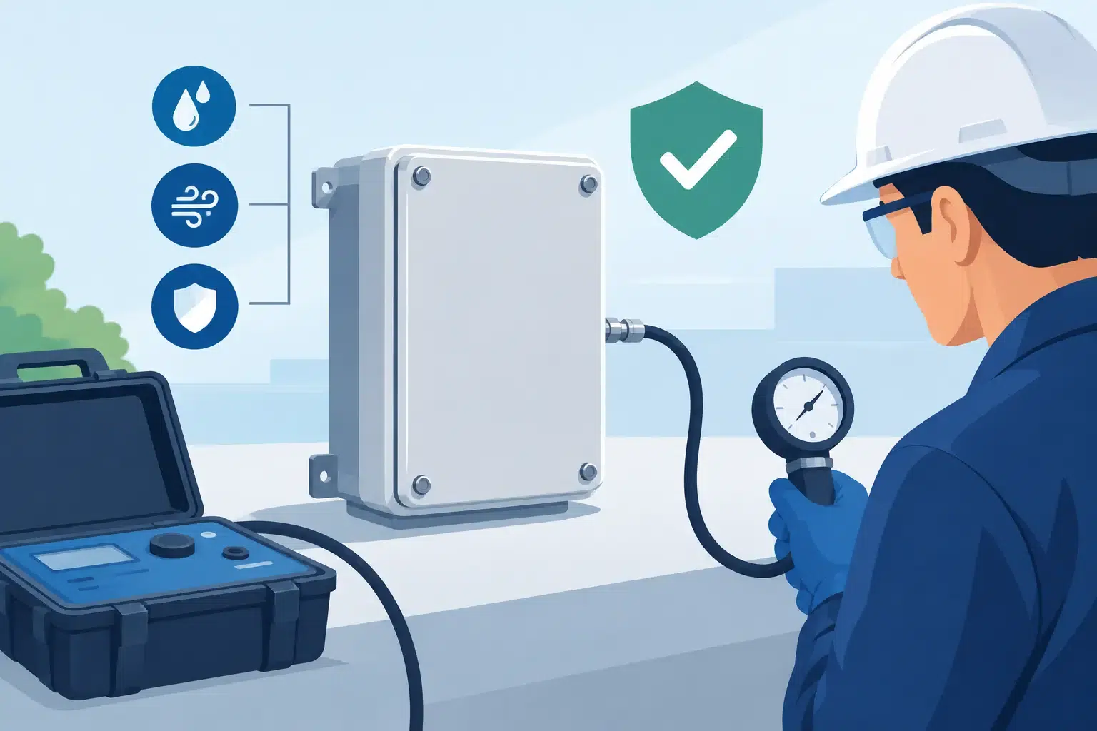
For total-flooding clean-agent and inert-gas systems, the protected enclosure is part of the extinguishing system. If the room leaks too quickly, the design concentration may not remain in place for the required hold period. Room-integrity testing, often called a door-fan test, assesses leakage and predicts retention performance without discharging agent.
This is particularly relevant where the room has raised floors, ceiling voids, cable penetrations, ducts or frequent contractor activity. Remedial sealing may be required around services, doors or construction joints. The practical trade-off is clear: sealing must support agent retention without creating unacceptable operational issues, such as preventing necessary ventilation or access.
Where an inert-gas system creates an enclosure pressure concern, over-pressure vents must also be inspected and tested in line with the design. These are not optional accessories. Incorrectly sized, obstructed or poorly installed vents can damage the enclosure or prevent it from performing as calculated.
Decide whether agent discharge testing is appropriate
A full discharge test can provide valuable assurance, but it is not automatically the right acceptance test for every installation. It can involve considerable cost, operational downtime, clean-up or recharge planning, and may be impractical in a live data centre or production environment.
The required approach should be defined early with the client, designer, insurer and relevant stakeholders. In many cases, a carefully controlled functional release test verifies the releasing circuit and output operation without opening the extinguishing-agent containers. This is supported by checks of cylinder pressure or weight, pipework installation, nozzle placement, hydraulic calculations, room integrity and documented factory or site tests.
Where a live discharge is specified or justified, it needs a detailed method statement and risk assessment. The area must be controlled, affected people briefed, emergency arrangements agreed and all interfaces managed. CO2 discharge testing demands particularly stringent controls because of the risk to life. No test should be arranged merely to create a dramatic demonstration.
Witness the tests and record the evidence
The acceptance record should allow a future competent engineer, insurer or auditor to understand exactly what was installed and what was demonstrated. It should include test results, device identities, cause-and-effect results, room-integrity data where required, cylinder details, certificates, drawings, operating instructions and any outstanding items.
Before handover, the responsible team should receive a practical demonstration of normal, alarm, fault, isolate and reset conditions. They need to know who can isolate the system before intrusive works, how impairments are controlled, when to call for service support and why a release must never be reset without investigating the cause.
A useful handover pack normally contains at least the following:
- the final system drawings and approved cause-and-effect matrix;
- commissioning and acceptance test certificates;
- room-integrity and pressure-relief evidence where applicable;
- operating instructions, emergency procedures and maintenance requirements; and
- a record of training, defects, variations and agreed completion actions.
Common issues that delay handover
The most frequent problems are rarely major equipment failures. More often, they are coordination issues: unsealed cable penetrations, a damper that does not close on command, inaccessible manual controls, incorrect labels, missing interface confirmation or late changes to the protected room.
Another common weakness is treating acceptance as the end of responsibility. Fire suppression systems protect changing environments. New racks, altered ceiling tiles, revised ventilation, building works and changed occupancy can all affect performance. The acceptance test establishes a verified baseline, but regular inspection and maintenance are what preserve it.
For organisations managing several sites, a consistent impairment process is particularly valuable. If a system is isolated for maintenance, contractors should know who authorises the isolation, what compensating measures apply and who verifies reinstatement. The period when a critical room is unprotected should be visible and controlled, not left to an informal note.
Plan acceptance testing before installation begins
The best projects define the acceptance plan during design, not in the final week of installation. Early agreement on witness requirements, site access, shutdown windows, interface responsibilities and whether discharge testing is expected prevents costly late-stage decisions.
Active Fire Suppression approaches acceptance testing as part of the wider engineered delivery process: from agent selection and technical design through installation, room sealing, commissioning, demonstration and ongoing support. That continuity matters because the people testing the system understand the assumptions on which it was designed.
If your organisation is planning a new suppression system or upgrading a critical area, treat acceptance testing as the moment to ask difficult operational questions while the project team is still in place. Clear answers now are far more valuable than discovering a missing interface, leaking enclosure or unclear reset procedure when a real fire alarm occurs.
Leave A Comment
You must be logged in to post a comment.