

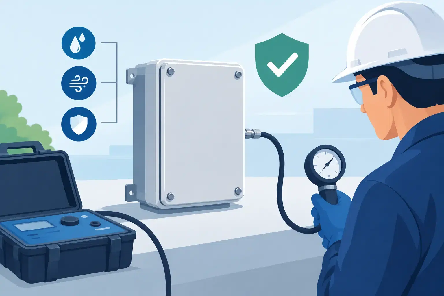
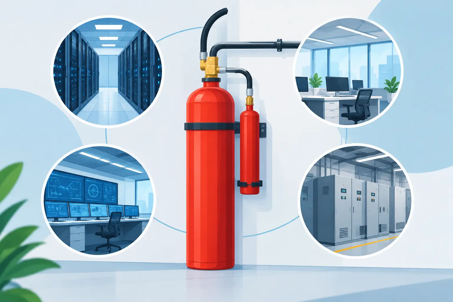
A gaseous fire-suppression system is only as effective as the room that contains its extinguishing agent. Knowing how to test enclosure integrity is therefore essential for any server room, data centre, control room, battery room or protected industrial enclosure. If the agent escapes through unsealed openings too quickly, the required concentration may not be held long enough to control or extinguish the fire – even where cylinders, pipework and detection are otherwise correctly installed.
What enclosure integrity testing proves
Enclosure integrity testing, commonly called a room integrity test or fan test, assesses how well a protected enclosure retains extinguishing agent following a system discharge. It is used with gaseous systems such as IG55, IG541, IG01, IG100, INERGEN®, Novec 1230 and HFC227ea systems including FM200 and FE227.
The test does not discharge the suppression system. Instead, calibrated fan equipment is fitted into an external doorway and used to measure the air leakage characteristics of the room. Specialist software uses those measurements, together with room dimensions, agent details and any pressure-relief arrangements, to predict the likely agent retention time.
For most total flooding systems, the design objective is to maintain the required extinguishing concentration for a minimum hold time, often ten minutes. The exact requirement depends on the system design, the hazard, the agent and the applicable standard. A room can look sealed during a visual inspection yet still leak sufficiently around cable penetrations, ceiling voids, doors or building joints to compromise performance.
That distinction matters operationally. In a data centre, a failed hold time can turn a contained incident into extended equipment loss and service interruption. In a process-control environment, it may affect safety, production capability and recovery planning. The integrity test provides evidence that the enclosure and suppression design work together as intended.
How to test enclosure integrity with a fan test
A competent engineer begins by confirming the room boundaries. This includes walls, floors, ceilings, raised access floors, suspended ceilings, service risers and connected voids. Where a false ceiling or floor forms part of the protected volume, it must be included in the calculations or effectively sealed from the enclosure. Missing a connected void can produce misleading results and leave a route for agent loss.
The room volume is then measured or verified against approved drawings. Accurate dimensions are vital because the predicted concentration and retention time rely on the protected volume being correct. The engineer will also identify the extinguishing agent, design concentration and required hold time from the system documentation.
Before testing begins, doors, dampers and other openings that would be closed during an actual discharge are placed in their normal fire condition. Mechanical ventilation and air-conditioning systems should be considered carefully. Any systems designed to shut down on discharge must be represented accordingly, while fire dampers and automated closures must be checked to ensure they operate as the design assumes.
A calibrated fan assembly is installed in a suitable doorway. The fan creates both positive and negative pressure within the room, while instruments measure airflow and pressure at several test points. These readings establish the leakage profile of the enclosure. The test equipment does not simply identify whether air leaks out; it characterises how the room behaves under pressure so that the retention calculation is meaningful.
Specialist software then estimates the agent retention time. It also considers the height of the protected enclosure and, where relevant, the expected height of the agent interface. This is particularly significant for agents and applications where maintaining a concentration at a defined level is part of the design basis.
The engineer should provide a clear report showing the room details, test conditions, leakage measurements, calculated retention time and pass or fail outcome. For a critical facility, this report is a useful part of the fire-suppression system record, supporting maintenance planning, insurer discussions and future alteration control.
Why pressure relief must be considered too
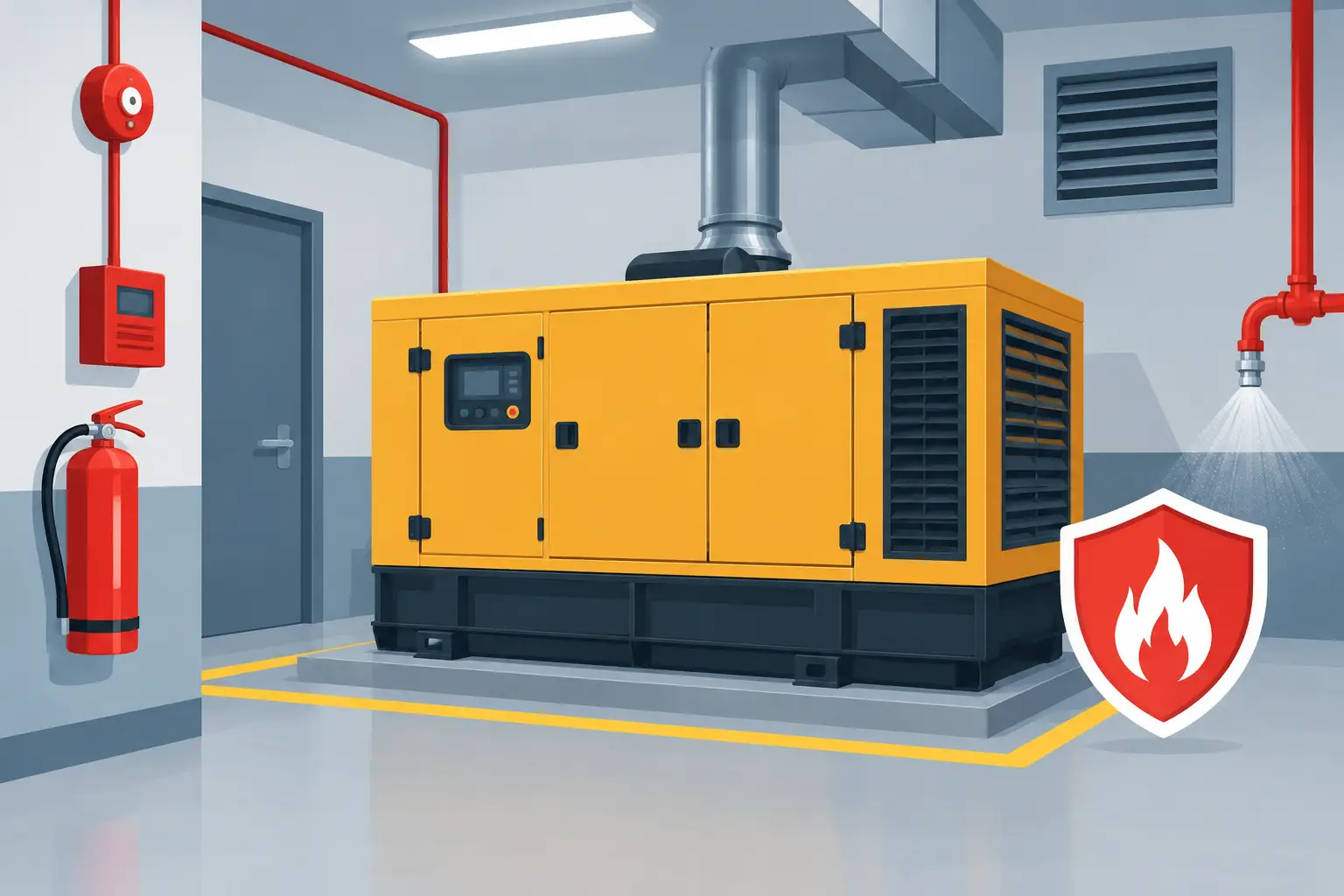
Room integrity is not solely about preventing leakage. A gaseous discharge can create a rapid pressure change inside the protected space. If this pressure is not relieved appropriately, it can damage doors, ceilings, partitions or glazing. Conversely, an incorrectly sized or poorly installed pressure-relief vent can become a significant leakage path.
The enclosure test and pressure-relief design must therefore be reviewed together. The required vent area depends on factors including the agent, quantity, discharge time, enclosure volume and structural pressure limits. It is not a detail to resolve after the suppression system has been designed.
A properly engineered solution balances two requirements that can appear to conflict: the room needs to retain the extinguishing concentration, while excess discharge pressure needs a controlled route to dissipate. This is one reason room sealing, vent selection and system commissioning should be coordinated by specialists rather than treated as separate trades.
Common reasons an enclosure fails
Most integrity failures are repairable, but finding the true cause requires a systematic approach. Cable trays and pipe penetrations are frequent sources of leakage, especially after IT, electrical or building-services work. Open-ended trunking, unsealed sleeves and gaps around containment can connect the protected room to adjacent spaces or ceiling voids.
Doors are another regular issue. Worn seals, poorly adjusted closers, thresholds and unsealed gaps around frames can have a material effect, particularly in smaller rooms. Access hatches, raised-floor edges, ceiling tile perimeters, louvre openings and construction joints can also contribute.
Changes made long after commissioning are often the underlying problem. A new data cable may appear insignificant, but several minor alterations can reduce the room’s retention performance. The same applies when an internal partition is moved, a ventilation route is changed or a fire door is replaced without considering its sealing performance.
Where a test fails, the right response is not to apply sealant indiscriminately. The engineer should interpret the results, inspect likely leakage paths and agree remedial works that maintain the room’s operational needs. A server room may require planned service penetrations; a plant room may need ventilation arrangements that cannot simply be sealed. In these cases, the solution may involve correctly rated dampers, automatic closures, purpose-designed sealing systems or a review of the protection strategy.
When should room integrity be retested?
Integrity testing should be completed at commissioning for a new or modified gaseous suppression system, and it should form part of the ongoing maintenance strategy. The appropriate interval can depend on the applicable standard, insurer requirements, the protected hazard and the extent of change within the room. Annual review is common, but a fixed calendar date should not be the only trigger.
Retesting is particularly advisable after building works, new cabling, changes to air-conditioning or ventilation, replacement of doors, alterations to ceilings or floors, or any work that penetrates the enclosure boundary. It is also sensible after a suppression discharge, following repairs to over-pressure vents, or when an inspection identifies damaged seals or unexplained changes in room pressure behaviour.
Facilities teams can make this easier by including the protected boundary in change-control procedures. Before contractors drill, core, cable or alter services within a suppression-protected space, they should understand that the enclosure itself is a life-safety and business-continuity component. Recording penetrations and arranging reinstatement testing prevents minor works becoming a hidden weakness.
Standards, documentation and competent testing
Gaseous suppression systems are generally designed, installed and maintained in accordance with standards such as BS EN 15004 and ISO 14520, alongside manufacturer guidance and project-specific requirements. The exact testing method and acceptance criteria should align with the system design and relevant standard.
Competence matters because a useful test is more than placing a fan in a doorway and printing a result. The engineer needs to understand agent concentration, enclosure geometry, pressure-relief provision, mechanical interfaces and the operational use of the room. They must also be able to distinguish between a straightforward sealing defect and a design issue requiring further engineering assessment.
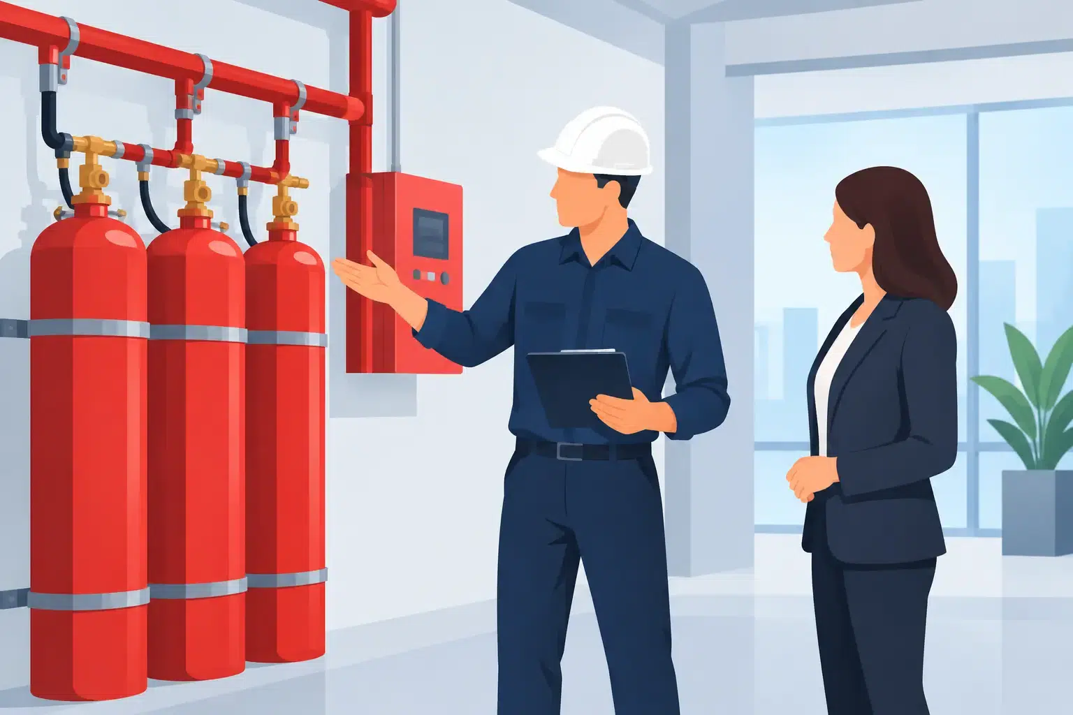
Active Fire Suppression can manage this process from enclosure review and remedial sealing through to room integrity testing, commissioning and ongoing maintenance. That joined-up approach avoids the common gap between a suppression installation and the building works needed for it to perform correctly.
A passing certificate should never be treated as permission to forget the room. Keep the test report with the suppression records, control alterations to the enclosure, and retest whenever its boundary changes. That practical discipline helps ensure the system will protect the people, equipment and continuity it was installed to safeguard.
Leave A Comment
You must be logged in to post a comment.