

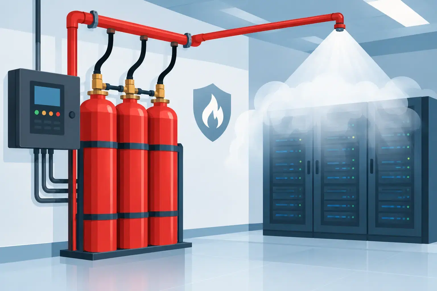
A fire suppression system is only as effective as the decisions made in the seconds before agent discharge. Suppression controls provide that decision-making layer, coordinating detection, alarms, warnings, equipment shutdowns and the release of extinguishing agent. For a server room, production area, battery enclosure or commercial kitchen, this sequence can determine whether a small incident becomes a prolonged and costly interruption.
The control equipment is not simply a panel on the wall. It is the interface between a site’s fire strategy and a physical response designed to protect people, critical assets and operational continuity. The correct arrangement depends on the extinguishing agent, the room or hazard being protected, the presence of people, and the consequences of either a delayed discharge or an unwanted discharge.
What suppression controls do
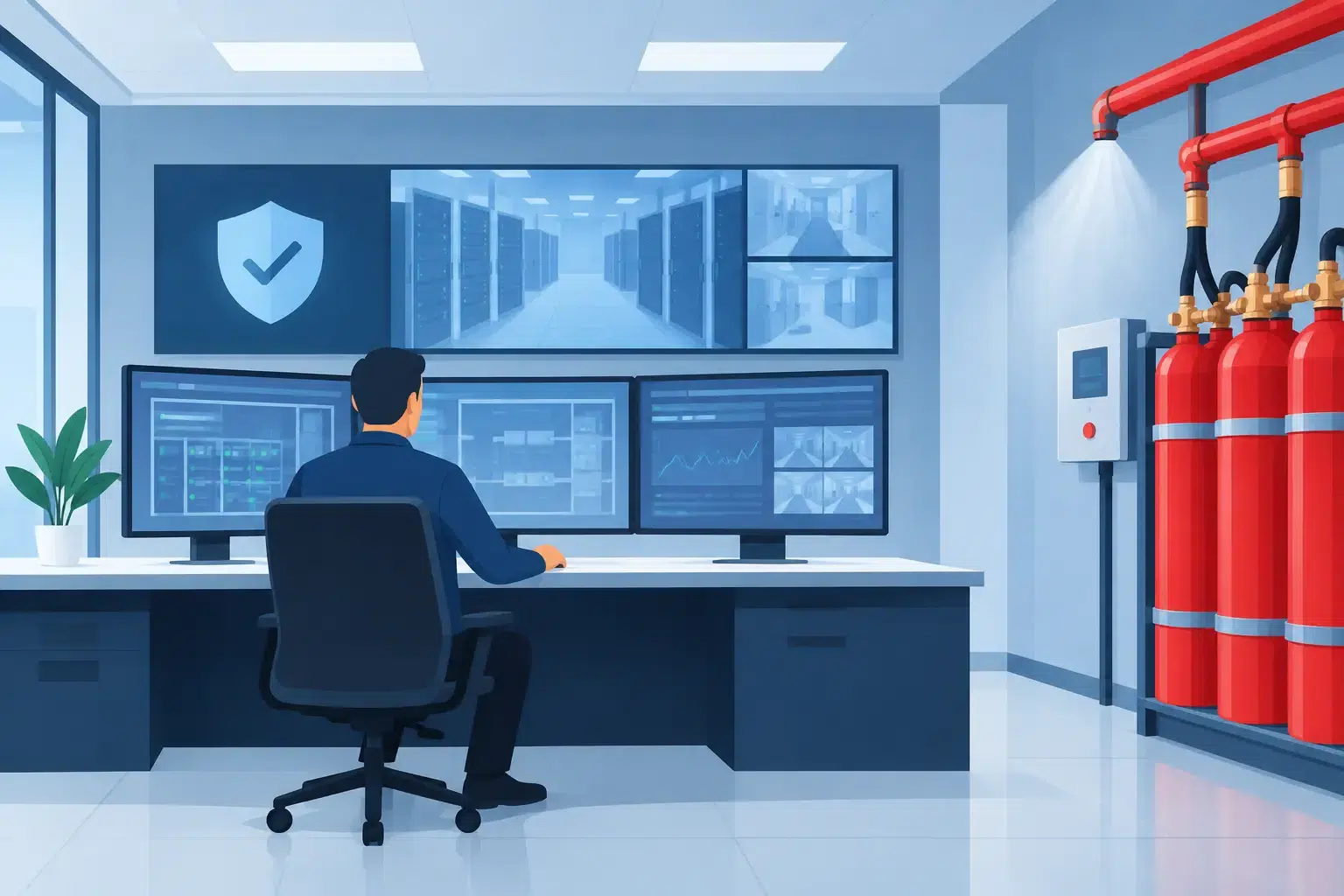
Suppression controls receive signals from automatic detection devices and use pre-programmed cause-and-effect logic to initiate the appropriate response. In many protected enclosures, detection is arranged in zones. A first detector operation may raise an alarm and prompt investigation, while confirmation from a second detector or detection zone begins the release sequence.
This approach reduces the likelihood that a single faulty detector, transient environmental condition or maintenance error will release an extinguishing agent unnecessarily. At the same time, it allows the system to respond automatically when a developing fire has been confirmed. The balance matters. A data centre may need very early warning and rapid intervention to prevent smoke damage and service interruption, while an occupied area requires additional safeguards before discharge.
A typical suppression control sequence can include alarm signalling, warning sounders and visual indicators, time delays, shutdown of air handling equipment, closure of dampers, equipment isolation and agent release. Once discharge has occurred, the controls can report the event to a fire alarm system, building management system or remote monitoring arrangement, subject to the agreed design.
The panel also supervises key circuits and system conditions. Faults affecting detection, manual release stations, sounders, actuator circuits, cylinders or interface connections should be identified clearly so they can be investigated before protection is compromised.
The release sequence must suit the risk
There is no universal release sequence that is suitable for every fire hazard. A well-designed system begins with understanding what must be protected, who may be present and what could intensify the fire.
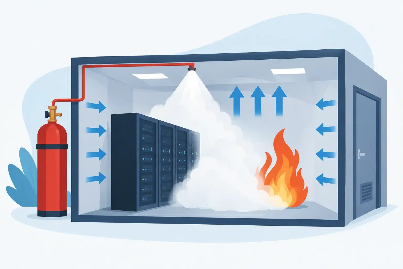
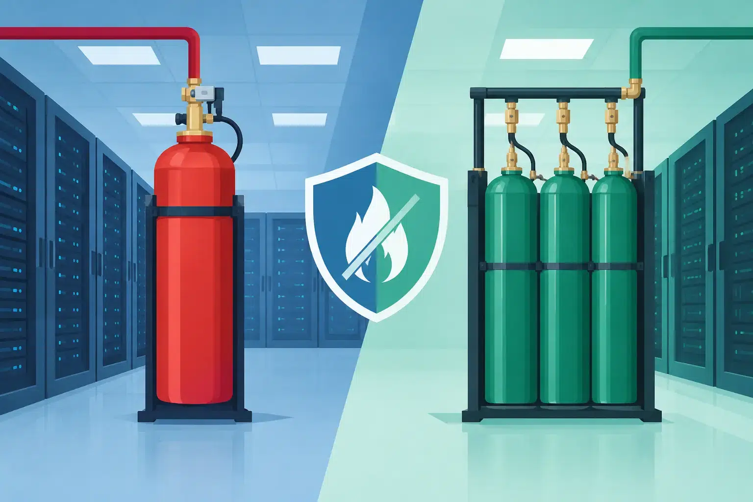
For inert gas and clean-agent systems protecting enclosed spaces, the control panel commonly provides a pre-discharge warning period. Audible and visual alarms warn anyone in or near the enclosure that agent release is imminent. This delay gives occupants time to leave safely, while supporting rapid automatic suppression once the hazard is confirmed.
In a room containing high-value IT equipment, the controls may also stop ventilation and close dampers before discharge. This helps retain the agent concentration needed to extinguish the fire. However, the exact timing and interfaces need careful engineering. Switching off critical equipment too early may itself affect operations, while leaving air movement running can reduce the effectiveness of the extinguishing concentration.
For commercial kitchens, wet-chemical suppression controls are configured around a different hazard. They may automatically shut off fuel or electrical supplies to cooking appliances while discharging agent across cooking surfaces, plenum areas and extraction ducts. The aim is to suppress a fire involving cooking oils and prevent fuel from continuing to feed it.
CO2 systems require particularly careful safety measures because carbon dioxide can present a serious life-safety risk in occupied or accessible areas. Warning devices, lock-off arrangements, signage, evacuation procedures and the design of any manual controls must be considered as part of the full system strategy. The right solution depends on the hazard and site access arrangements, not just the size of the protected room.
Detection logic: speed without unwanted discharge
Cross-zoned or coincident detection is widely used where avoiding accidental agent discharge is a priority. The release sequence starts only when separate detection inputs confirm the fire condition. Very early smoke detection, including VESDA systems, can provide an earlier warning stage before the suppression release criteria are met.
This arrangement is often valuable in data centres, electrical switchrooms and control rooms, where a false discharge could cause disruption, investigation costs and unnecessary system recovery work. Yet coincidence detection is not automatically the best answer in every application. Where fire growth is expected to be rapid, the detection and release strategy must be selected to achieve the required response time.
The design should document these decisions in a clear cause-and-effect matrix. Facilities teams need to know exactly what happens at each stage: alert, confirmed fire, pre-discharge warning, release, post-discharge condition and fault. Ambiguity during an incident is not acceptable.
Manual release, abort and emergency controls
Manual controls give trained people a way to act when automatic detection has not yet reached its release condition, or when a fire is clearly visible. A manual release unit may initiate discharge immediately or follow the programmed warning delay, depending on the system design and the safety requirements of the protected area.
An abort control is different. It is normally provided to delay or prevent agent release while a trained person assesses the situation during the pre-discharge stage. Its operation must be unambiguous, with suitable labelling and positioning. It should never be treated as a substitute for evacuation or as a way to routinely override a genuine alarm.
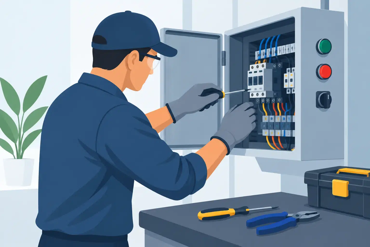
Control arrangements also need to account for isolation during servicing. Engineers must be able to test circuits, replace components and carry out planned maintenance without creating a discharge risk. Equally, the responsible person needs a clear indication whenever automatic release is disabled, along with a process for restoring the system promptly once work is complete.
Interfaces are where many weaknesses emerge
A suppression system rarely works in isolation. It may need to communicate with the building fire alarm system, HVAC controls, fire dampers, generators, extract systems, machinery, gas solenoids, access-controlled doors or monitoring systems. Each interface is important, but more interfaces also create more points of possible failure.
The practical question is not whether every available function can be connected. It is whether each connection supports the fire strategy and has been tested under realistic conditions. For example, closing dampers may be necessary to maintain agent concentration, but the arrangement must not obstruct safe egress. Shutting down a process may reduce fire growth, but it must be coordinated with operational safety procedures.
Commissioning should prove the full cause-and-effect sequence, not only the operation of individual devices. This includes alarms, delays, actuator circuits, shutdown outputs, feedback signals and fault reporting. Where a live discharge test is not appropriate, functional testing and agreed simulation methods should still demonstrate that the controls will perform as designed.
Controls cannot compensate for poor enclosure performance
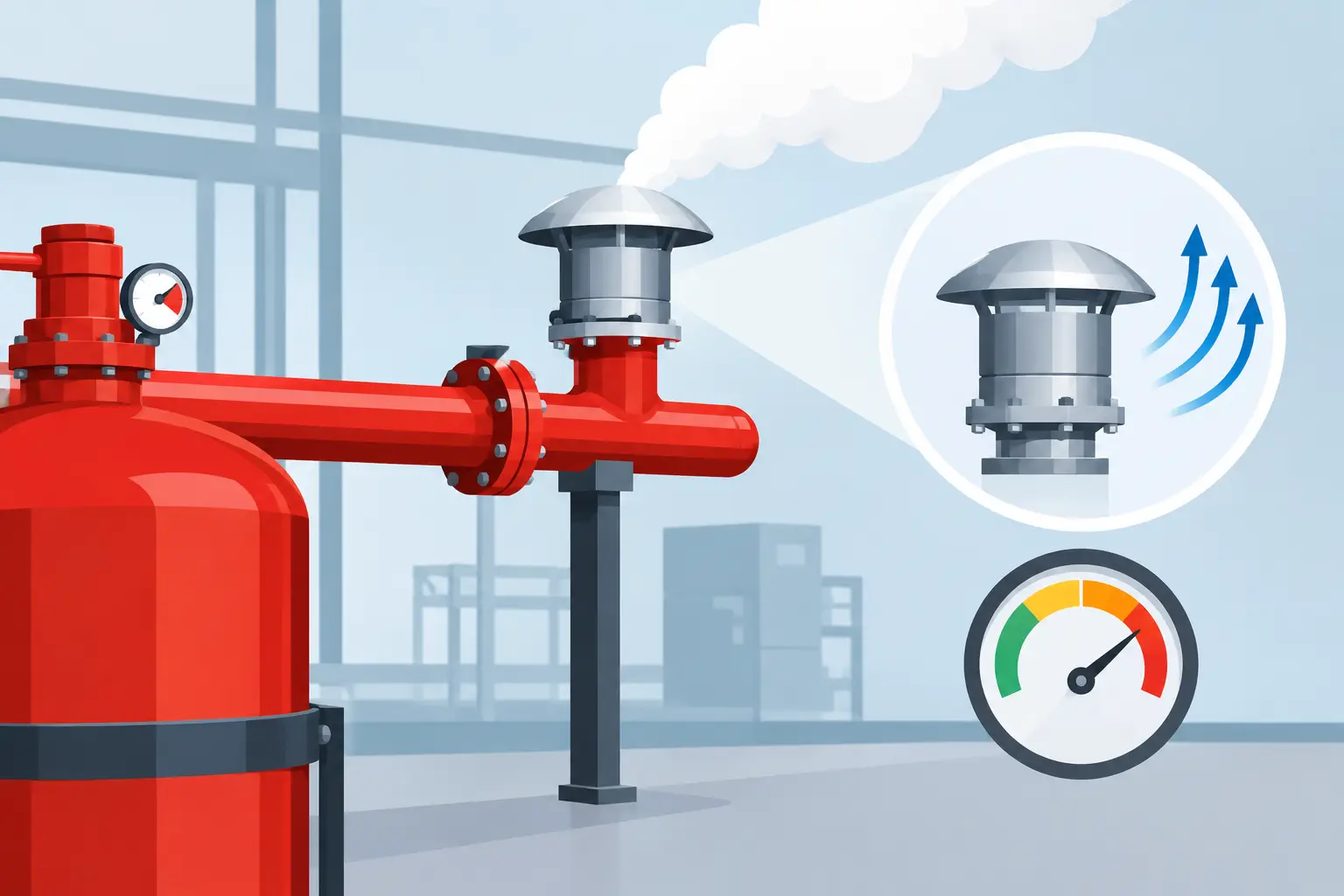
For gaseous fire suppression, the control panel can command a technically correct release, but the protected enclosure must still retain the agent for the required hold time. Open doors, unsealed cable penetrations, unprotected ductwork and poorly maintained dampers can all undermine system performance.
That is why room integrity testing and inspection of the enclosure are closely linked to suppression controls. A change as simple as installing new cabling, altering a ceiling void or adding ventilation can affect both agent retention and the control strategy. The suppression system should be reviewed whenever the room layout, use, occupancy or building services change.
Relevant standards, including BS EN 15004 for gaseous extinguishing systems and applicable control-panel standards, provide a framework for design, installation and maintenance. Insurer requirements, manufacturer instructions and the site’s own emergency arrangements must also be considered. Compliance is not a paperwork exercise. It is evidence that the system has been engineered and verified for the hazard it is intended to control.
Maintaining reliable suppression controls
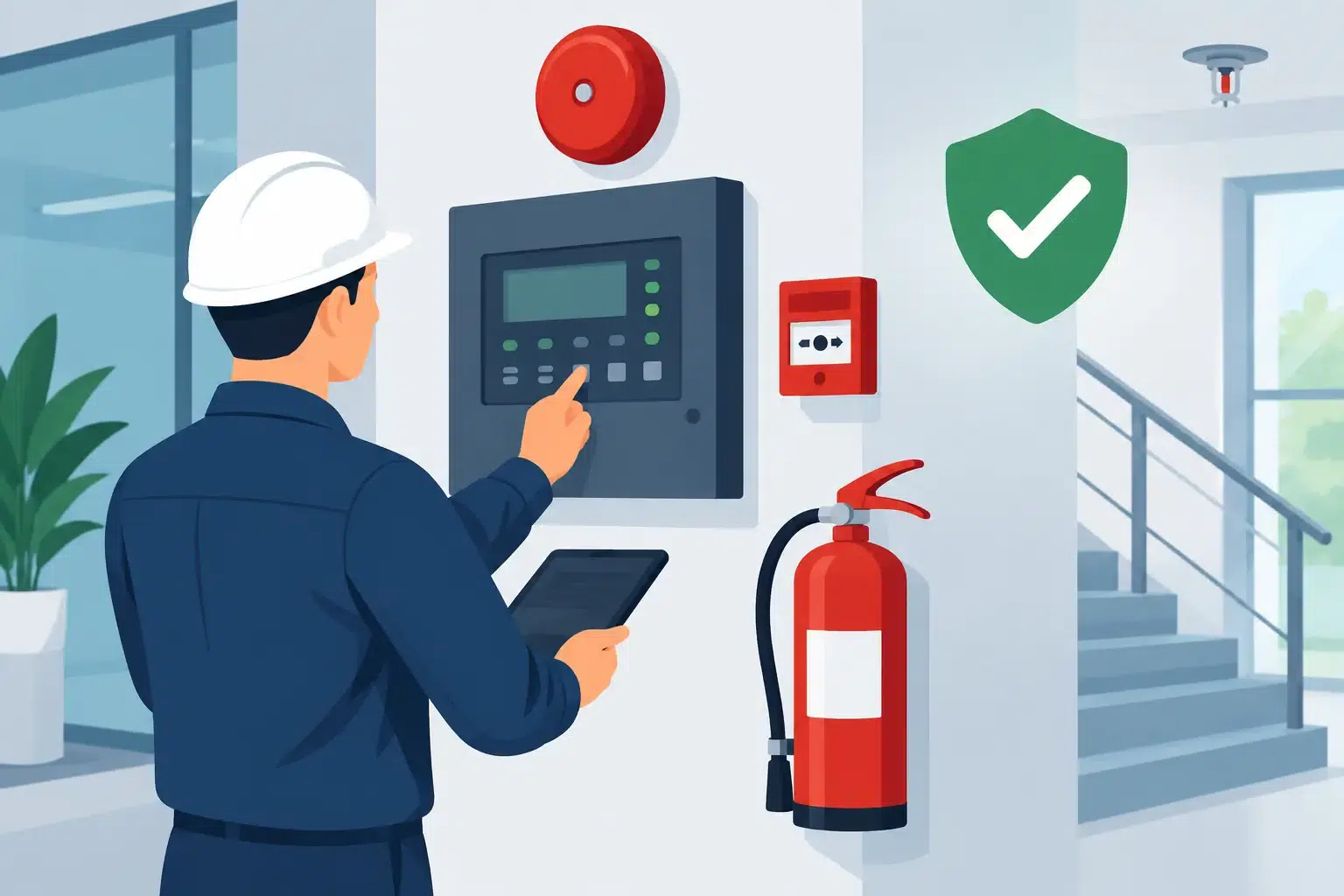
Suppression controls need planned inspection and testing throughout their service life. Batteries, fuses, detector circuits, warning devices, manual stations, interfaces and panel indications all require attention. Faults should be acted upon promptly, particularly where they affect automatic release, pre-discharge warning or essential equipment shutdowns.
Site teams can support reliability by keeping control panels accessible, protecting manual controls from damage, maintaining accurate zone plans and reporting any building alteration that affects the protected area. They should also ensure relevant staff understand the warning signals, evacuation requirements and escalation process following a system event.
Active Fire Suppression Ltd can design, commission and maintain integrated suppression controls as part of a complete fire detection and extinguishing solution. The most useful starting point is a practical discussion about the hazard, the people who use the space and the downtime the business cannot afford. From there, the control sequence can be made clear, testable and fit for the way the site actually operates.
Leave A Comment
You must be logged in to post a comment.