

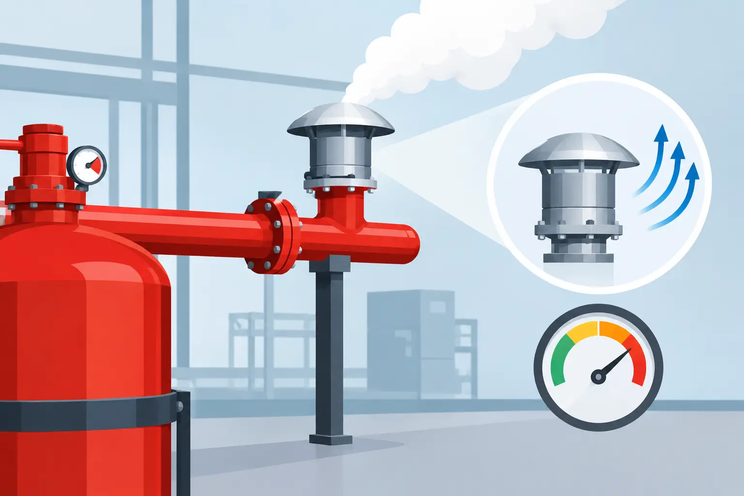
A gaseous fire-suppression discharge can protect a server room, control room or process enclosure in seconds. It can also create a rapid pressure change that the room fabric was never designed to withstand. Understanding how to size pressure vents is therefore not a finishing detail after the suppression system has been selected. It is a core part of making sure the enclosure, the system and the people using the space are protected.
Pressure relief vents, also called pressure vents or pressure-relief dampers, provide a controlled route for displaced air and agent during discharge. Correct sizing helps prevent excessive positive pressure within the protected enclosure and, where relevant, damaging negative pressure as the agent cools or the room is subsequently ventilated. The calculation must be based on the actual system and building conditions, not an assumed vent area or a rule of thumb.
Why pressure vent sizing matters
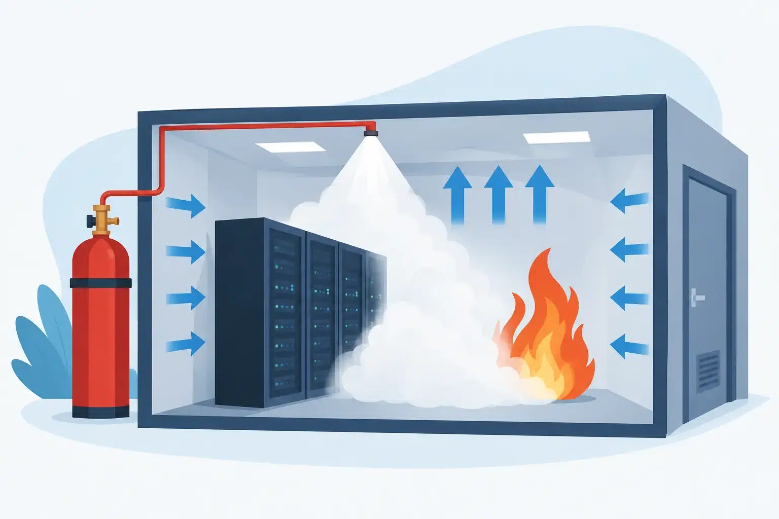
When an inert gas, clean agent or carbon dioxide system discharges, a large volume of extinguishing agent enters the protected room quickly. That incoming volume displaces the air already in the enclosure. If it has nowhere to go, room pressure rises. Doors may be forced open, lightweight partitions can deform, ceiling tiles may lift and glazed elements, ductwork or building seals can be damaged.
The reverse effect can also matter. Following discharge, cooling of the gas mixture, leakage from the enclosure and operation of extract or air-conditioning equipment can create negative pressure. In a room with a low structural pressure tolerance, that inward pressure can be just as significant as the initial outward pulse.
For critical environments, the consequences go beyond physical damage. A failed door seal or damaged wall penetration can compromise enclosure integrity and reduce the hold time required to maintain the extinguishing concentration. In a data centre or electrical room, this creates avoidable uncertainty at the point when continuity matters most.
Pressure vents are not intended to make an unsuitable room acceptable. They are one element of an integrated gaseous suppression design that also considers enclosure strength, door construction, structural openings, room sealing, ventilation shut-down and post-discharge arrangements.
How to size pressure vents for gaseous suppression systems
The required free vent area is calculated from a pressure-relief assessment. This models the discharge characteristics of the selected extinguishing system against the protected enclosure and its allowable pressure limits. It is generally undertaken using approved manufacturer software or specialist calculation methods associated with the relevant suppression standard.
The starting point is the agent. IG-55, IG-541, IG-01, IG-100, INERGEN®, Novec 1230, HFC227ea and CO2 do not all behave in the same way during discharge. Cylinder pressure, nozzle design, discharge time, agent quantity and the required design concentration all affect the rate at which gas enters the room. An inert-gas system, for example, often has a high flow rate and may demand a substantial relief path even in a relatively modest enclosure.
The calculation then considers the net volume of the enclosure. This is not simply the length, width and height of the room. Permanent equipment, raised-floor voids, suspended ceilings, cable voids and connected spaces may all affect the volume that must be protected or relieved. If a floor void is included within the protected hazard, it may need its own pressure-relief consideration depending on the arrangement and separation.
The enclosure’s maximum permissible pressure is equally critical. This value should be established from the construction rather than guessed. A reinforced concrete plant room may tolerate more pressure than a lightweight partitioned comms room, but even seemingly solid spaces can contain weak points such as glazed screens, fire doors, ceiling systems or proprietary panels. The lowest credible pressure rating of the enclosure components should guide the design.
A proper assessment also uses the system’s discharge profile, including the peak gas-flow rate. The vent must have enough effective free area to keep the predicted pressure below the allowable limit throughout the relevant discharge period. A vent’s nominal face size is not the same as its free area. Louvres, blades, grilles, insect mesh, weather protection and duct connections can all restrict flow. The calculation must account for the resistance of the complete relief path.
Positive and negative pressure relief
Most discussions focus on positive pressure because it occurs during the main discharge. This is the condition that can push doors, walls and ceilings outwards. The pressure vent is commonly configured to open outwards for this reason, allowing displaced air and agent to pass safely to an adjacent space or external location.
However, the design should assess negative pressure too. Some installations require bi-directional relief, or separate arrangements, to prevent an enclosure being pulled inwards after discharge. The right answer depends on the agent, enclosure leakage, the presence of mechanical ventilation and the structural limits in both directions.
This is one reason why a simple single-blade vent selected from a catalogue is not a reliable solution. The vent needs to open at the intended pressure, provide the calculated free area and respond appropriately to the expected direction of pressure change.
Where the vent discharges is part of the calculation
A pressure-relief vent should not discharge into a location that creates a new operational or life-safety risk. The receiving area must be capable of accepting the flow without causing excessive pressure there. If the vent discharges into a corridor, ceiling void, plant space or adjoining room, that space may need to be assessed as part of the pressure-relief route.
This point is particularly significant for CO2 systems. Carbon dioxide presents an asphyxiation hazard at elevated concentrations, so any discharge route and adjacent occupancy must be considered carefully. Warning arrangements, lock-offs, signage and any required post-discharge ventilation should form part of the wider system design.
For clean agents and inert gases, personnel safety and operational access still matter. A relief route should not direct high-velocity flow towards workstations, escape routes, sensitive equipment or areas where it could disturb dust and debris. External discharge can be appropriate, but weather protection, security and building-envelope detailing must then be addressed.
Design inputs that are often missed
Vent sizing is accurate only when the project information is accurate. Changes made after the calculation can invalidate the result. A new partition, replacement fire door, sealed cable penetration or altered air-conditioning layout can materially change how the room responds during discharge.
The most useful information for the design team includes the confirmed room drawings, construction details, door and glazing specifications, ceiling and floor arrangements, ventilation schematics, equipment layout and the intended use of adjacent spaces. It is also necessary to establish what happens automatically on alarm and discharge. Supply and extract fans will often need to shut down, while fire dampers and motorised dampers need to move to their correct position without obstructing the planned relief route.
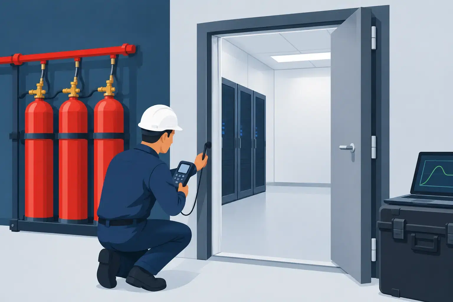
Room integrity testing has a different but related role. A door-fan test assesses whether the protected enclosure is sufficiently sealed to retain the extinguishing concentration for the required hold time. It does not replace pressure-relief calculations, and a correctly sized pressure vent does not prove room integrity. Both are required to demonstrate that the enclosure can survive discharge and retain the agent long enough to extinguish the fire.
Installation details can undermine a correct design
A vent calculation can be technically sound and still fail in practice if the installation does not match it. The installed vent must have the specified orientation, blade operation, free area and pressure characteristics. It should not be reduced by an unapproved grille, filter, mesh or duct alteration.
The surrounding opening also requires careful coordination. Structural supports, fire stopping, wall linings and weathering details must not restrict movement of the damper blades or introduce leakage routes that compromise the enclosure. Where a vent passes through a fire-resisting element, the fire strategy and product certification must be reviewed so that pressure relief does not weaken compartmentation.
Commissioning should confirm that the vent is installed as designed, opens in the correct direction and is not obstructed. This is also the time to verify cause-and-effect interfaces: HVAC shut-down, damper positions, door releases, alarms and any post-discharge purge arrangements. A suppression system is only as reliable as these connected functions.
Standards-led design, not estimated vent area
In the UK, gaseous fire-suppression systems are commonly designed in accordance with BS EN 15004 and, where applicable, related manufacturer approvals and insurer requirements. International projects may also be governed by ISO 14520 or NFPA 2001. The applicable standard, agent manufacturer guidance and the building’s specific constraints should be considered together.
There is no universal vent area per cubic metre of room volume. Two rooms of identical volume can require very different pressure-relief arrangements because their allowable pressures, agent systems, discharge rates, construction and relief routes differ. Treating vent sizing as a standard building-services detail can put both the enclosure and the suppression performance at risk.
For new installations, the strongest approach is to include pressure-relief design at the earliest stage, alongside agent selection and enclosure construction. For an existing protected room, it is worth reviewing the vent arrangement whenever cylinders are upgraded, the room is refurbished, ventilation is altered or a room-integrity test identifies changes in leakage behaviour. Active Fire Suppression can coordinate this work from suppression design through installation, commissioning and ongoing maintenance, so responsibility does not fall between trades.
A pressure vent may look like a modest component in the wall, but it protects the conditions that allow a gaseous system to do its job. Before approving a vent size, confirm the enclosure limits, discharge data and complete relief path with a competent suppression specialist. That conversation can prevent structural damage, preserve agent hold time and give critical operations a far more dependable recovery position after a fire event.



Leave A Comment
You must be logged in to post a comment.