

A gaseous fire-suppression system can be correctly designed, installed and commissioned, yet still fail to protect the risk if the enclosure leaks too quickly. Knowing how to test room integrity is therefore not an administrative exercise. It verifies whether the extinguishing concentration will remain in a protected server room, electrical switchroom, control room or process enclosure long enough to control a fire and prevent costly interruption.
For inert gas, clean-agent and carbon dioxide systems, the integrity of the room is part of the suppression system. Walls, ceilings, floors, cable routes, doors, dampers and pressure-relief arrangements all influence whether the design concentration can be held following discharge. A room-integrity test provides a measured answer without releasing agent into the protected space.
What a room-integrity test actually proves
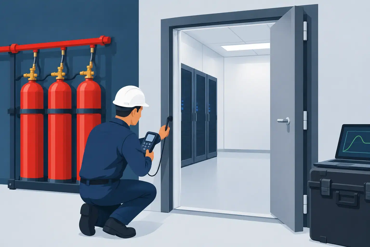
Room-integrity testing, often called an enclosure-integrity or door-fan test, measures the leakage characteristics of a protected enclosure. A calibrated fan is temporarily fitted into an external doorway. The tester uses it to create controlled pressure differences between the room and its surroundings, then records the airflow needed to maintain those pressures.
Specialist software combines the measured airflow with the enclosure volume, the protected height, the required design concentration and the system agent. It calculates the predicted retention time: the period for which the required extinguishing concentration should remain above the protected height after discharge.
This matters because suppression agent is not intended simply to fill a room. It must achieve a specified concentration and retain it for the duration set by the applicable design standard and risk assessment. Ten minutes is a common retention-time criterion for many total-flooding systems, but it is not a universal rule. The required performance must be established for the particular hazard, agent and system design.
A passing test demonstrates that the enclosure is sufficiently sealed for the stated design conditions. It does not replace the commissioning checks for detection, control panels, pipework, nozzles, cylinders, warning devices, manual controls or pressure-relief vents. Those elements must be verified as part of a properly managed installation and maintenance regime.
When should you test room integrity?
The first test should take place once the enclosure and its building services are complete enough to represent normal operating conditions, normally before final handover of a gaseous fire-suppression system. Testing too early can create a misleading result if later works introduce penetrations for data cabling, containment, HVAC controls or security equipment.
Retesting is advisable after any alteration that could affect the seal of the protected room. Common examples include new cable trays, replacement fire doors, ventilation upgrades, ceiling works, partition changes, raised-floor alterations and new pipe or conduit penetrations. A small unsealed route beneath a floor or above a suspended ceiling can have a material effect on retention time.
Planned periodic testing should also be considered within the maintenance strategy, particularly where an enclosure changes regularly or business continuity is critical. Data centres, communications rooms, production-control spaces and energy infrastructure often have live services modified over time. The test interval should reflect the likelihood of change, insurer expectations and the site’s risk-management arrangements.
Preparing the enclosure for a meaningful test
Good preparation is what makes the result useful. The room must be in its operational state, with doors, access hatches, ceiling tiles, floor panels and service openings in the condition they would be during an actual discharge. If a normally closed door is wedged open for the test, or a ventilation damper is left in a position it would not occupy after an alarm, the calculated retention time will not represent the real event.
Before testing, the responsible engineer should confirm the room dimensions and protected height, including voids that form part of the protected volume. Raised floors and ceiling voids cannot be ignored where agent can enter them or leakage paths pass through them. The installed agent, design concentration and required hold time should also be checked against the suppression-system documentation.
Mechanical ventilation requires particular attention. Air-handling systems may need to shut down on release, and dampers may need to close to isolate the enclosure. Their intended fire-condition position must be understood and, where practical, replicated or verified for the test. A room may appear well sealed while the fan is running, but fail the moment an unsealed damper path is exposed.
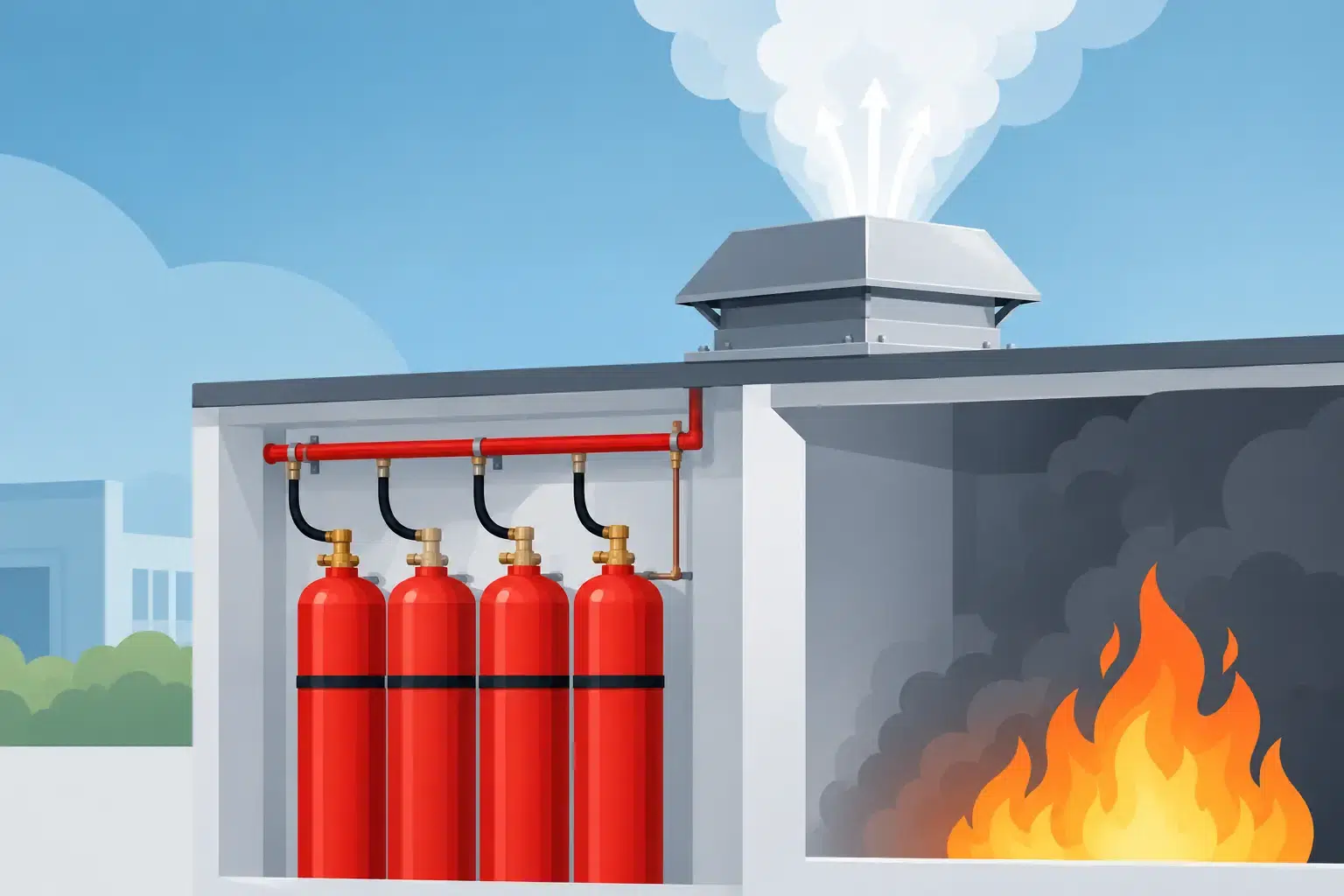
The engineer will also review the over-pressure relief provision. When a gaseous system discharges, room pressure can rise rapidly. Pressure-relief vents protect the enclosure fabric and are selected as part of the system design. They must not be sealed simply to improve a test result. The objective is compliant retention time without compromising the safe management of discharge pressures.
How to test room integrity using a door fan
A competent specialist begins by surveying the enclosure and identifying obvious leakage routes. The door fan is then installed in a suitable external doorway with an adjustable fabric panel that seals the remaining opening. The arrangement allows airflow to be measured accurately while keeping the rest of the room in its normal state.
The fan applies a sequence of controlled pressures, typically in both directions where required by the test method. Measurements are taken at several pressure points to establish the relationship between airflow and leakage. Rather than relying on a visual inspection alone, this provides quantified evidence of how the room will behave under the pressure changes associated with an agent discharge.
The measured data is entered into recognised enclosure-integrity calculation software. The calculation considers the characteristics of the agent and identifies the predicted concentration-decay profile. The output should state whether the enclosure achieves the required retention time, along with the assumptions used for volume, protected height, agent concentration and leakage path.
Testing should be carried out in accordance with the relevant system standard and the project specification. Depending on the system and application, this may include the principles in BS EN 15004, ISO 14520, NFPA 2001 or other client, insurer and authority requirements. The appropriate standard is not a substitute for engineering judgement: unusual rooms, mixed-use enclosures and complex ventilation arrangements may need additional assessment.
Interpreting a pass, a fail and borderline result
A pass means the calculated retention time meets or exceeds the specified criterion for the documented enclosure condition. The test report should be retained with the system records so future maintenance providers, auditors and insurers can see the basis on which performance was accepted.
A fail does not necessarily mean the suppression design is wrong. More often, it identifies a practical building-fabric issue. Common leakage routes include poorly sealed cable penetrations, gaps around door frames, unsealed floor voids, loose ceiling tiles, openings behind equipment, service risers and dampers that do not close fully. Thermal imaging, smoke pencils and targeted pressurisation checks can help locate harder-to-find leaks.
Borderline results deserve action as well. A room that only just achieves the required retention time may fail after the next IT installation, electrical modification or facilities project. Where business continuity is essential, it is sensible to address known leakage routes and create a reasonable margin rather than treating the minimum calculation as a permanent guarantee.
Rectifying leakage without creating a new problem
Sealing works must preserve the building’s fire compartmentation, acoustic requirements, service access and operational ventilation. The right solution may be a tested fire-stopping system around cables, suitable seals to doors and frames, correctly specified grommets, or repair to damper controls. Applying generic mastic to every visible gap is not an engineered answer and can obstruct future maintenance or breach other performance requirements.
Once remedial works are complete, the enclosure should be retested. The final report should record the successful calculation and any assumptions about dampers, vents and shutdown sequences. This gives facilities teams a clear baseline when planning future changes.
For complex sites, an integrated approach is usually the most efficient route. A specialist that understands agent selection, enclosure sealing, pressure relief, controls and commissioning can resolve the interfaces between disciplines instead of leaving the customer to coordinate separate contractors. Active Fire Suppression Ltd applies that approach from initial risk discussion through testing, demonstration and ongoing support.
A room-integrity test is best treated as a live performance check, not a one-off certificate. Keep the final report accessible, brief contractors before they open a penetration, and make retesting part of the change-control process. That practical discipline helps ensure the suppression system will perform as designed when the room is under the greatest pressure.



Leave A Comment
You must be logged in to post a comment.