

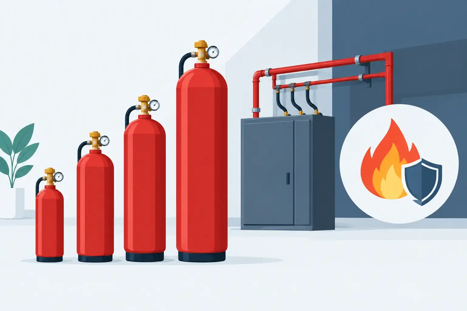
A protected server room may look straightforward on a drawing, yet a single unsealed cable penetration or an overlooked underfloor void can change the quantity of extinguishing agent required. A gas cylinder sizing guide is therefore not a catalogue exercise. It is a disciplined design process that establishes how much agent is needed, how it will reach the risk, and whether the enclosure can retain it long enough to control a fire.
For commercial premises, getting this right protects more than equipment. It helps limit smoke, heat and water damage, avoids unnecessary interruption to critical services, and provides evidence that the system has been designed around the actual risk rather than a nominal room size.
What gas cylinder sizing really means
In fixed gaseous fire suppression, cylinder sizing starts with the required mass of extinguishing agent. The number, capacity and arrangement of cylinders follow from that calculation, together with the chosen operating pressure, available plant-room space and discharge arrangement.
The objective is to discharge a proven concentration of agent into a defined enclosure within the required time. For inert gases, this commonly means a rapid discharge to achieve the design concentration throughout the protected volume. Clean-agent and carbon dioxide systems have their own design concentrations, discharge criteria and application limitations. A cylinder bank that is too small may not deliver the required concentration; one selected without proper hydraulic design may discharge unevenly or create unacceptable pressure effects.
The cylinder label alone does not tell the full story. Two rooms with the same floor area can need very different quantities of agent because of ceiling height, voids, temperature, leakage paths, hazard type and the agent selected.
The information needed before cylinders can be selected
A reliable design begins with a detailed survey and clear understanding of what must remain operational after an incident. The engineer needs the dimensions of the enclosure, including raised floors, suspended ceilings, service risers and any connected spaces that could allow agent to escape or require protection.
Establish the true enclosure volume
The starting point is the gross volume of the protected enclosure. This is usually calculated from length, width and height, but the process must account for irregular shapes, sloping ceilings and linked voids. Permanent, substantial objects may be considered in line with the relevant design standard, but this is not an opportunity to remove every cabinet and item of equipment from the calculation. Conservative, standards-led treatment of obstructions is essential.
A data suite is a common example. The room itself may be modest, but the raised access floor and ceiling void can form part of the enclosure. If they are open to the room and capable of carrying smoke or agent, they generally need to be included in the design. Protecting only the occupied room volume can leave a fire beneath cabinets or above the ceiling insufficiently covered.
Define the hazard and the agent
The agent is selected around the fire risk, occupancy, environmental policy, operational requirements and insurer expectations. Inert gas agents such as IG55, IG541, IG01, IG100 and INERGEN® are widely used for data centres, electrical rooms and other critical facilities. They reduce oxygen to a level that controls combustion while retaining a breathable atmosphere for a limited evacuation period when designed correctly.
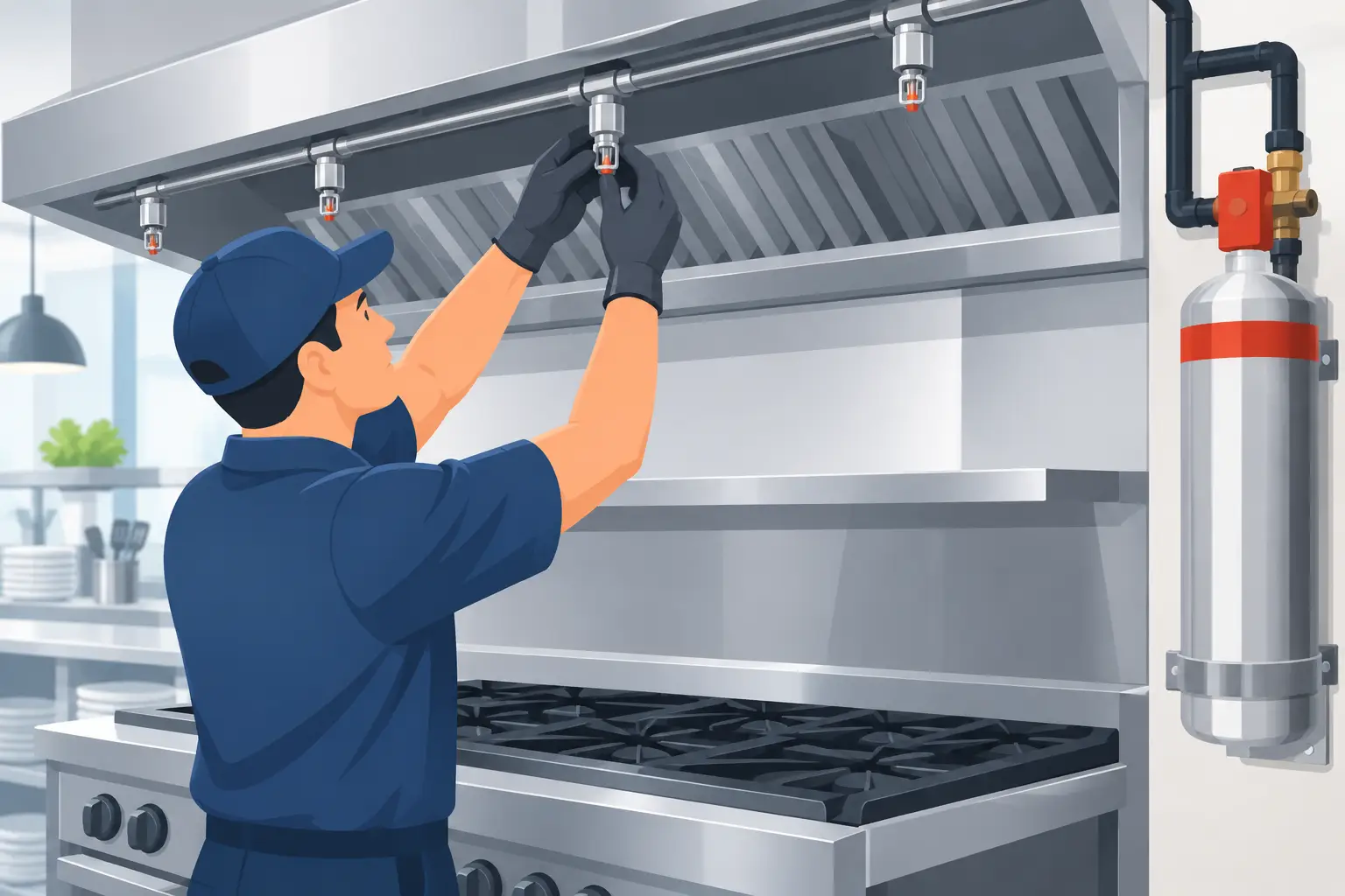
Clean agents, including Novec 1230 and HFC227ea, can offer a compact cylinder arrangement for suitable applications. Carbon dioxide is highly effective for certain unoccupied or closely controlled industrial hazards, but it presents serious life-safety considerations and demands stringent safeguards. Wet-chemical and dry-powder systems are selected for different hazard types, such as commercial kitchens and specialist industrial processes, rather than as substitutes for a room-flooding gaseous system.
Each agent has a defined design concentration based on the fuel and protection objective. A Class A surface fire, flammable-liquid hazard and deep-seated fire may require different approaches. The correct question is not simply, “Which cylinders fit in the cupboard?” It is, “Which extinguishing method controls this specific fire before it compromises people, assets or operations?”
Consider temperature, altitude and enclosure conditions
Agent quantity is affected by ambient temperature and, where relevant, altitude. These conditions influence gas volume and design concentration. A plant room that runs warmer than an office environment, or a site at elevated altitude, should not be treated as a standard room without assessment.
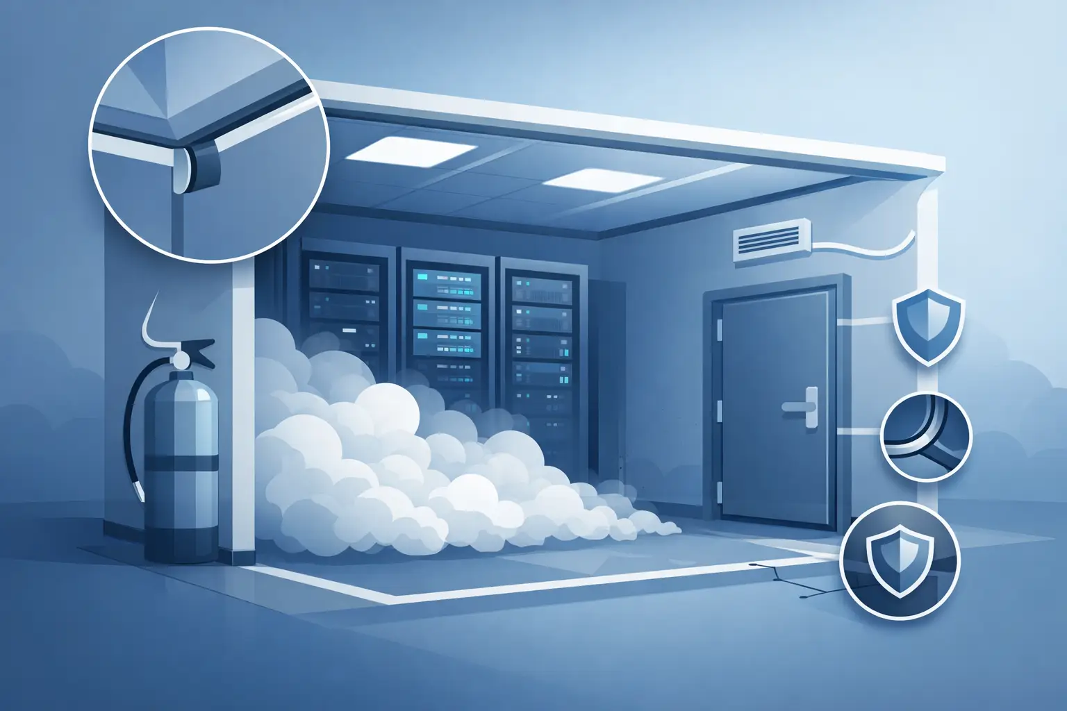
The condition of the enclosure also matters. Doors, dampers, cable openings, drainage routes and building interfaces all affect whether the agent remains at concentration after discharge. Room integrity testing is not an optional final-stage formality. It verifies whether the enclosure can retain the agent for the required holding period and identifies leakage that could undermine an otherwise correctly sized system.
A practical gas cylinder sizing guide for project planning
Facilities and project teams do not need to perform final hydraulic calculations themselves, but understanding the sequence makes early decisions more productive. A competent designer will typically work through the following connected stages:
- survey the protected enclosure and identify every relevant void, opening and connected space;
- agree the hazard classification, protection objective and suitable extinguishing agent;
- calculate the required agent mass using the applicable design standard and environmental conditions;
- select cylinder capacity, fill density and storage pressure to provide the calculated agent quantity;
- design the pipework and nozzles to deliver the agent within the required discharge time; and
- confirm pressure-relief, room integrity, detection, controls, alarms and shutdown interfaces.
This sequence explains why a preliminary budget can be prepared from room dimensions, but a final cylinder schedule should follow a site survey and engineering design. Early figures are useful for planning. They should not be mistaken for a commissioned design suitable for installation.
Cylinder capacity, pressure and floor-space trade-offs
Cylinder banks are available in different capacities and storage pressures. Higher-pressure inert gas cylinders can reduce the number of containers required, which may be valuable where space is restricted. However, higher pressure also affects the pipework design, manifold arrangement, handling requirements and discharge pressure within the enclosure.
More smaller cylinders may assist access, phasing or future expansion, while fewer larger cylinders can simplify the footprint. Neither option is automatically better. The practical answer depends on the available cylinder-store location, access route, structural loading, maintenance clearance and the way the building is expected to develop.
Cylinder location is not merely an architectural decision. Remote cylinder banks require pipework that remains hydraulically capable of delivering the designed flow at every nozzle. Long runs, changes in direction, pipe diameter and nozzle orifice sizing all influence performance. A system cannot be validated by agent mass alone.
For protected areas with changing layouts, such as data halls or production rooms, allowance may also be needed for future expansion. This should be a deliberate design decision rather than an assumption that spare cylinders can simply be added later. Additional cylinders may require changes to manifold capacity, pipe sizing, pressure relief and control programming.
Discharge pressure and over-pressure relief
When a gaseous agent enters an enclosure quickly, it displaces air and can create a pressure change. Without suitably designed pressure relief, this can damage walls, ceilings, doors or glazing, particularly in lightweight construction.
Pressure-relief vent sizing is calculated alongside the suppression system, taking account of agent flow, room strength and whether both positive and negative pressure effects need consideration. The vent must also discharge to a safe location. It is not enough to install a louvre where there is space if it compromises compartmentation, security or weather protection.
This issue often emerges late in refurbishment projects, when the suppression design is ready but the building fabric has not been considered. Addressing relief requirements during coordination with mechanical, electrical and architectural teams prevents avoidable delays and costly alterations.
Detection, controls and shutdowns affect the design outcome
Cylinders are only one part of an automatic suppression system. Detection must identify a developing fire reliably, controls must manage alarm and release logic, and connected equipment may need to shut down or change state before discharge. In a server room, this can include air-handling systems, dampers and power arrangements. In an industrial enclosure, it may involve fuel isolation, conveyor stoppage or process shutdown.
A common arrangement uses cross-zoned detection to reduce the likelihood of unwanted discharge, followed by a warning period that allows occupants to leave before agent release. The exact cause-and-effect strategy must suit the risk and applicable standards. It should be demonstrated during commissioning, not left as an untested assumption in a control-panel programme.
Very early warning smoke detection, including VESDA, can provide valuable time to investigate and intervene before a fire grows. It does not remove the need to size the suppression system correctly, but it can strengthen the overall protection strategy for high-value and continuity-critical spaces.
Standards, testing and ongoing confidence
Gaseous systems should be designed, installed and maintained to the applicable standards and manufacturer requirements. Depending on the system and application, this may include BS EN 15004, ISO 14520, BS 5306-4 for carbon dioxide systems, and relevant product and control-system standards. Insurer requirements and client specifications may add further obligations.
After installation, commissioning verifies cylinder pressures, pipework, nozzles, detection, controls, alarms and interfaces. Room-integrity testing then provides practical confirmation that the enclosure can retain the extinguishing concentration for the intended period. These activities are central to system performance, not paperwork added after the work is complete.
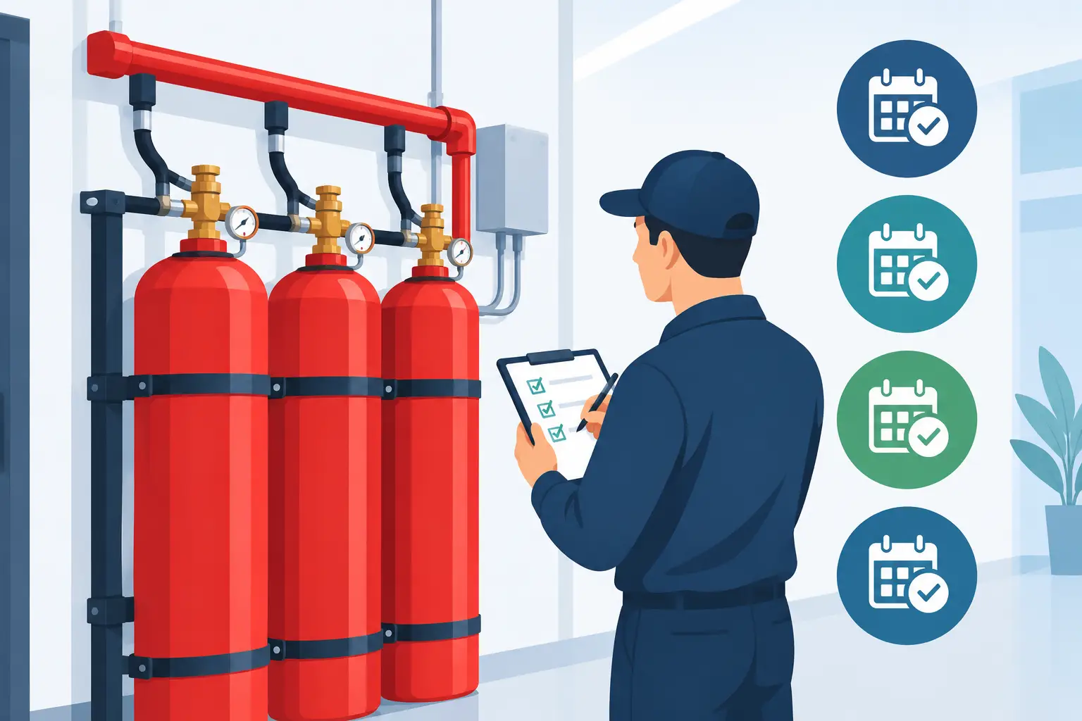
Cylinder contents, pressures, hoses, valves and control equipment also require planned inspection and maintenance. Changes to room use, partitions, ventilation, cable routes or ceiling voids should trigger a review. A correctly sized system can become unsuitable if the protected enclosure changes around it.
The most useful starting point is a proper conversation about the room, the fire risk and the operational consequence of loss. Active Fire Suppression can then turn that information into an engineered design that considers agent selection, cylinder storage, discharge performance, enclosure integrity and long-term support as one coordinated responsibility.


Leave A Comment
You must be logged in to post a comment.