

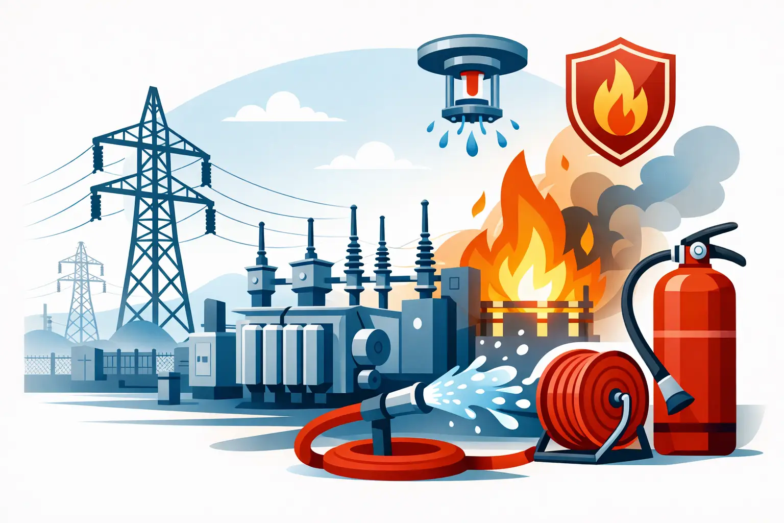
A transformer fire can take a substation out of service in minutes, but its commercial effects can continue for months. Replacement lead times, network constraints, lost production and insurer scrutiny can turn a localised equipment failure into a major continuity event. Effective fire protection for electrical substations is therefore not simply about raising an alarm. It is about detecting the right fire scenario early, controlling it without creating further electrical risk, and helping the site return to service safely.
The right approach depends on the equipment, its location, the insulating medium used, occupancy and the consequences of an outage. A protection strategy for an enclosed GIS room will look very different from one for an outdoor oil-filled transformer. That distinction matters from the first risk discussion.
Start with the substation fire risks
Substations contain several potential ignition sources: overloaded connections, cable faults, overheating switchgear, arc flash events, failed bushings, battery faults and transformer insulation breakdown. Where mineral oil is present, a small electrical failure can develop into a high-energy, fast-spreading fire with intense radiant heat and significant smoke production.
Not every substation carries the same risk profile. Air-insulated switchgear, gas-insulated switchgear, control rooms, protection relay rooms, battery rooms and transformer compounds should be assessed as separate but connected hazards. The fire load, ventilation, access arrangements and electrical isolation procedures may all differ.
A practical design also considers what sits beyond the room or compound. Cable routes can carry fire between areas. Smoke entering a control room can damage relays and communications equipment even where the main fire is contained. A discharge that is suitable for an unoccupied enclosure may be inappropriate where personnel need to enter routinely.
The aim is to establish credible fire scenarios rather than specify an extinguishing agent by habit. This gives the design team, site operator and insurer a sound basis for decisions about detection, suppression, containment and recovery.
Fire protection for electrical substations needs layers
Automatic suppression is most effective when it is part of a coordinated system. Detection identifies an abnormal condition, controls manage alarms and releases, suppression limits fire growth, and interfaces help place affected equipment into a safe state. Physical measures such as fire-rated separation, cable sealing, oil containment and drainage complete the picture.
Early warning before a developing fault becomes a fire
Conventional smoke detection can be appropriate in some ancillary rooms, but substations often demand more targeted detection. Aspirating smoke detection, commonly known as VESDA, can identify very low levels of smoke in clean control, relay and switchgear environments. This provides an opportunity to investigate an overheating component or insulation fault before a full fire develops.
Flame detection is often better suited to transformer bays and other areas where a flame may develop rapidly or where environmental conditions make smoke detection less reliable. Detector selection and positioning must account for line of sight, sunlight, vibration, dust, steam and the layout of equipment. Detection that is theoretically compliant but poorly located will not provide dependable protection.
For a suppression release system, detection is commonly arranged on a confirmed-fire basis, using coincident signals from separate detectors or zones. This reduces the likelihood of an unwanted discharge while retaining a fast response to a genuine event. Audible and visual pre-discharge warnings, manual release points, abort controls and clear evacuation procedures are all part of safe system operation.
Suppression that matches the enclosure and hazard
For enclosed electrical rooms containing sensitive equipment, clean-agent and inert-gas systems can provide rapid automatic suppression without the residue associated with powder or foam. Inert gases such as IG55, IG541, IG01 and IG100 reduce oxygen concentration to a level that will not sustain combustion, while being designed around defined occupied-space safety limits. They can be well suited to sealed switchgear, relay and control rooms where minimising collateral damage is a priority.
Clean agents, including HFC227ea/FM200/FE227 and Novec 1230 systems where appropriate to the project, can also be considered for enclosed spaces. Agent choice should reflect the enclosure volume, ambient conditions, storage cylinder location, environmental policy, insurer expectations and future servicing requirements. It should not be based on a claim that one agent is universally best.
CO2 has a proven role in certain industrial and electrical applications, particularly in unoccupied or tightly controlled spaces. However, it presents a serious life-safety hazard at extinguishing concentrations. Its use demands rigorous assessment, controls, warning arrangements, lock-off procedures and staff training. Where routine access is required, an alternative agent or a different protection approach may be more suitable.
Outdoor oil-filled transformers call for a different conversation. Total-flooding gas systems are not designed to protect an open transformer compound. These risks may require water spray or deluge arrangements, fire barriers, bunding, oil drainage and separation distances, supported by suitable flame detection and electrical control interfaces. The exact scope should be coordinated with the transformer manufacturer, electrical designer, fire engineer, network operator and insurer.
Room integrity is a performance requirement
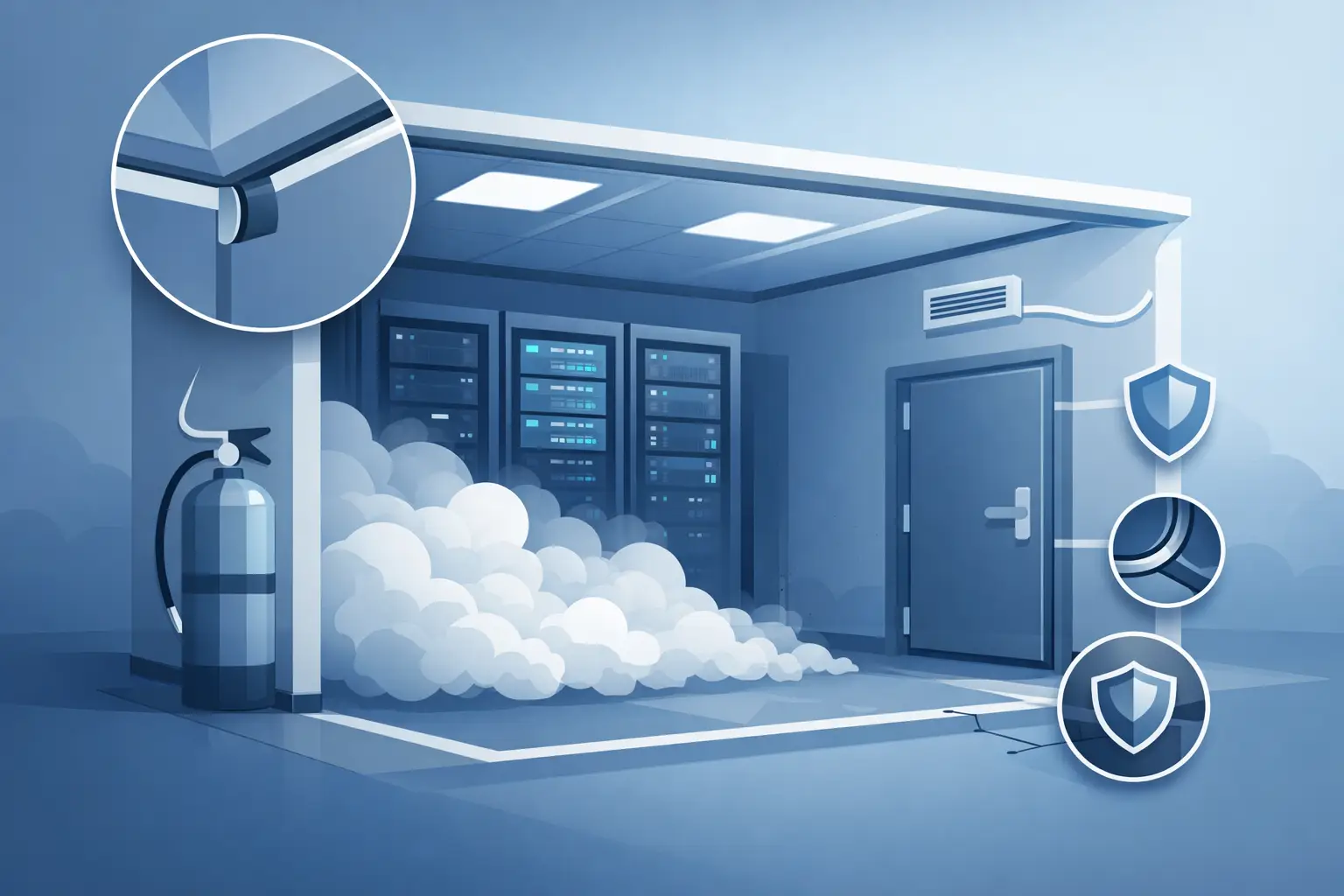
A gaseous suppression system relies on the design concentration being achieved and held for the required period. Doors, cable penetrations, dampers, raised floors, ceiling voids and building joints can all allow agent to escape. In a substation, cable routes are a frequent source of unplanned leakage.
This is why room sealing and room-integrity testing are central to system performance, not optional finishing work. A door fan test identifies whether the protected enclosure can retain the extinguishing concentration for the specified hold time. If the room fails, remedial sealing or pressure-relief measures may be needed before acceptance.
Over-pressure vents also deserve careful design. A rapid discharge changes room pressure. Without an appropriately sized vent, the enclosure or doors may be damaged, or the system may not perform as calculated. The vent location must not compromise the protected area or create a risk to people outside it.
Controls and shutdowns must be agreed before installation
A suppression system cannot decide on its own how a substation should respond to fire. The cause-and-effect programme needs agreement with the people responsible for electrical operations. Depending on the risk assessment, a confirmed fire may initiate alarms, close dampers, stop ventilation, isolate non-essential equipment, signal a building management system, notify a monitoring centre or trip defined electrical plant.
There are trade-offs. Immediate shutdown can limit escalation and support suppression performance, but an unnecessary trip can interrupt a critical process. Delaying isolation may preserve output briefly, but allow fault energy to continue feeding the incident. The appropriate sequence depends on system topology, resilience, standby capacity, safe operating procedures and the impact of losing that particular asset.
These interfaces should be witnessed during commissioning, not left as assumptions in drawings. Site teams need a clear demonstration of what will happen on pre-alarm, confirmed alarm, discharge, fault and manual release.
Standards, testing and maintenance protect the investment
Fixed suppression and detection systems should be designed, installed and maintained to applicable standards and manufacturer requirements. Depending on the system and application, this may include BS EN 15004 for gaseous extinguishing systems, BS 5839-1 for fire detection and alarm systems, relevant British Standards, European standards, insurer guidance and project-specific electrical requirements.
Compliance documentation is valuable, but the ongoing condition of the system matters just as much. Detection heads can become contaminated, cylinders can require periodic checks, interfaces can be altered during electrical works, and room sealing can be compromised by a new cable installation. Regular inspection, functional testing, repairs and periodic room-integrity testing help identify these changes before a fire exposes them.
Maintenance should also include a review of site operating procedures. If access arrangements, occupancy, equipment loading or the use of the protected room changes, the original suppression design may need reassessment.
Build protection around recovery, not only discharge
The strongest substation fire strategy considers the hours after an incident. Can operators safely confirm isolation? Is there a defined route for restoring control functions? Are critical spares available? Will smoke contamination affect adjacent panels or communications equipment? Are alarm signals received by people who can act at any hour?
Active Fire Suppression Ltd approaches these questions as part of an engineered, end-to-end project: from risk discussions and agent selection through installation, sealing, commissioning, demonstration and planned support. For sites where downtime is costly, that ownership reduces the risk of gaps between fire protection, building works and electrical operations.
A well-designed system will not remove every consequence of a serious electrical fault. It can, however, give a developing incident less time to become a prolonged outage – protecting people first, limiting damage where possible and giving the business a more controlled path back to operation.


Leave A Comment
You must be logged in to post a comment.